background image

Herrtronic

®

 RDU-D Supplement

I n s t a l l a t i o n ,   O p e r a t i o n ,   &   M a i n t e n a n c e   M a n u a l

13

www.herrmidifier-hvac.com

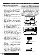
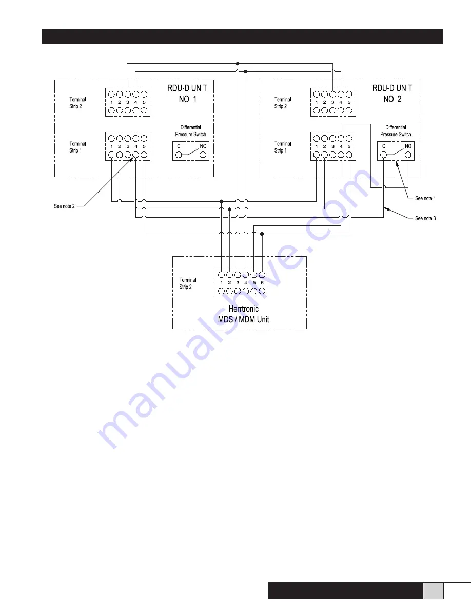
Figure 18 - MDS/MDM Control to (2) RDU-D Units

Notes:

1.  Disconnect wire number (16) from the common terminal of the differential pressure switch in the RDU-D unit 

number (2). Remove the spade connector and cap with a wire nut.

2.  Disconnect Blue wire number (5) from terminal strip number (1) on RDU-D unit number (1) remove the spade 

connector and cap with a wire nut.

3.  This wire is connected to RDU-D unit number (1) at terminal strip number (1). Position number (4) to the  

RDU-D number (2) common terminal of the differential pressure switch.

Summary of Contents for Herrtronic RDU-D

Page 1: ...Engineered Humidification Systems H e r r m i d i f i e r w w w h e r r m i d i f i e r h v a c c o m Herrtronic RDU D Supplemental Manual...

Page 2: ...ns 4 III Installation Preparation 4 Unit Clearances 4 IV Direct Mount Option 5 MDS with Direct Mount RDU 5 MDD with Direct Mount RDU 5 V Remote Mount Option 6 MDS with Remote RDU 6 MDD with Remote RDU...

Page 3: ...NCLUDING IMPLIED WARRANTIES OF MERCHANTABILITY AND FITNESS FORPARTICULAR PURPOSE The foregoing shall constitute the total liability of seller in the case of defective performance of all or any of the...

Page 4: ...igure 2 Overall Dimensions III INSTALLATION PREPARATION WARNING Disconnect power to the humidifier while installing RDU The RDU unit must either be placed higher than the Herrtronic unit or provisions...

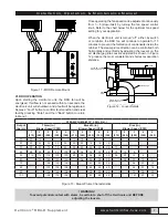
Page 5: ...nto the Herrtronic unit 7 Fasten the RDU in place using four 8 32 self tapping screws installed from inside the Herrtronic cabinet 8 Replace the RDU cover fan speed control knob 9 Insert the condensat...

Page 6: ...low spots the length should be trimmed so that it can extend 1 into the grey plastic fill tee in the Herrtronic unit 12 National state or local electrical codes may require the use of two separate co...

Page 7: ...horizontally and vertically by adjusting the louvers on the air discharge grille Louvers adjusted as shown in Figure 12 produce the most consistent and shortest evaporation distance Figure 12 Louver D...

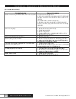
Page 8: ...2 Check fuses in RDU 3 Check wiring to fan 4 Check voltage to fan should be 220 VAC 10 5 Replace fan and capacitor Fan speed adjustment not working 1 Replace rheostat Water spitting out of manifold 1...

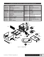
Page 9: ...er RDU D 1T 2T for 380 EST 1416 Fuseholder DH 052 Foam Tape EST 1417 Fuse 1 A EST 230 Steam Hose EST 1447 1 EST 1447 2 Manifold Assembly Specify Unit Model Number EST 353 Bushing EST 531 5 Pole Termin...

Page 10: ...ronic RDU D Supplement I n s t a l l a t i o n O p e r a t i o n M a i n t e n a n c e M a n u a l 10 www herrmidifier hvac com H2 FOR 460V INPUT H3 FOR 600V INPUT Figure 15 RDU D with 460 600V Transf...

Page 11: ...Herrtronic RDU D Supplement I n s t a l l a t i o n O p e r a t i o n M a i n t e n a n c e M a n u a l 11 www herrmidifier hvac com Figure 16 RDU D with 380V Transformer...

Page 12: ...Herrtronic RDU D Supplement I n s t a l l a t i o n O p e r a t i o n M a i n t e n a n c e M a n u a l 12 www herrmidifier hvac com Figure 17 RDU D w o Transformer...

Page 13: ...terminal of the differential pressure switch in the RDU D unit number 2 Remove the spade connector and cap with a wire nut 2 Disconnect Blue wire number 5 from terminal strip number 1 on RDU D unit n...

Page 14: ...d Humidification Systems Form No OM 102 09 13 Herrmidifier 2013 All Rights Reserved Herrmidifier 101 McNeill Rd Sanford NC 27330 P 800 884 0002 F 800 458 2379 www herrmidifier hvac com cs herrmidifier...

Reviews: