background image

Einbauhinweis 51305650

www.herthundbuss.com 2

Stecker

Pol-Anzahl: 13
Spannung:  24 V

1.   Mehradriges Kabel (Teil 1) ca. 30 mm ab-

manteln, Einzeladern 7 mm abisolieren 
und verzinnen.

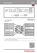
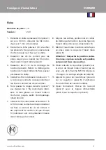
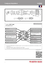
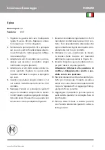
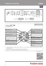
2.   Stecker (Teile 2–9) demontieren und Tei-

le 2–5 lagerichtig in der dargestellten Rei-
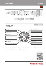
henfolge (s. Abb.) auf Kabel schieben.

3.   Kontaktschrauben für benötigte Pole zum 

Einführen der Einzeladern in Stifteinsatz 
(Teil 8) lösen.

4.  

Die 2 Schrauben der Zugentlastung 
(Teil 6) lösen. Zugentlastung vom Stiftein-
satz abziehen und über Kabel schieben.

5.   Innere Einzeladern Nr. 1–4 in zugehörige 

Kontakte stecken und Kontakt-schrauben 
festziehen.

6.  

Isolierring (Teil 7) über die 4 inneren 
Einzeladern schieben, auf den Stiftein-
satz stecken und ganz niederdrücken bis 
eine spürbare Verrastung erfolgt. (Abbil-
dung A)

7.   Äußere Einzeladern Nr. 5–13 in zugehöri-

ge Kontakte stecken und Kontaktschrau-

ben festziehen. Dabei ist unbedingt 
darauf zu achten, dass jede Einzelader 
vollständig in die Kontaktbohrung einge-
führt wird.

8.   Kabel ausrichten, Zugentlastungsschelle 

in den Stegen des Stifteinsatzes positio-
nieren und festziehen. (Abbildung B)

9.   Den so montierten Stifteinsatz in Körper 

für Stifteinsatz (Teil 9) einstecken.   
Achtung! Kodierstellung beachten. Kor-
rekter Sitz ist nur in einer Stellung mög-
lich.

10.  

Anschließend Kappe (Teil 5) mit dem 
Körper für Stifteinsatz verschrauben und 
mit einem Gabelschlüssel SW 36 festzie-
hen. (Nach „Überdrehung“ ist richtiger 
Festsitz erreicht.)

11.  Gummitülle (Teil 4) an Kappe (Teil 5) an-

fügen (Gleitmittel empfehlenswert).

12. 


Überwurfmutter (Teil 

2) mit Gleitring 

(Teil 3) auf Kappe (Teil 5) fest anschrau-
ben.

Summary of Contents for ELPARTS 51305650

Page 1: ...ELPARTS Einbauhinweis Steckdose ...

Page 2: ...cken und ganz niederdrücken bis eine spürbare Verrastung erfolgt Abbil dung A 7 Äußere Einzeladern Nr 5 13 in zugehöri ge Kontakte stecken und Kontaktschrau ben festziehen Dabei ist unbedingt darauf zu achten dass jede Einzelader vollständig in die Kontaktbohrung einge führt wird 8 Kabel ausrichten Zugentlastungsschelle in den Stegen des Stifteinsatzes positio nieren und festziehen Abbildung B 9 D...

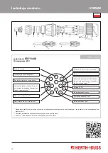
Page 3: ...tmals für andere Funktionen genutzt 3 Die Kontakte 11 und 12 sind nur bei einem ADR System angeschlossen Steuerung Anhängerbremse 2 Bremsleuchten Rechte Schlussleuchte Umriss leuchte Begrenzungsleuchte und Kennzeichenleuchte 1 Abfüllsicherung 3 Linke Schlussleuchte Umriss leuchte Begrenzungsleuchte und Kennzeichenleuchte 1 Armaturenschrankbeleuchtung 3 Nebelschlussleuchte Fahrtrichtungsanzeiger re...

Page 4: ... internal single cores put it on the pin insert and press it down until a lock is felt Fig A 7 Plug the external single cores nos 5 13 into the associated contacts and tighten them by the contact screws By all means it must be ensured that each single core is entered into the contact bore com pletely 8 Centre the cables position the strain re lief clip in the links of the pin insert and tighten th...

Page 5: ...today 3 Contacts 11 and 12 are only connected in an ADR system Trailer brake control 2 Stop lights Right hand taillight position light marker light and licence plate light 1 Overspill protection 3 Left hand taillight position light marker light and licence plate light 1 Fittings cabinet lighting 3 Rear fog light Right hand direction indicator light Axle lifting device Left hand direction indicator...

Page 6: ...r sur l insert mâle et l enfoncer jusqu à sentir l encliquetage illustration A 7 Insérer les fils individuels extérieurs n 5 à 13 dans les contacts correspondants et les fixer en serrant les vis de contact Il est important de veiller à ce que chaque fil individuel soit complètement inséré dans l alésage de contact 8 Aligner les câbles positionner le collier de décharge de traction dans les tiges d...

Page 7: ... d autres fonctions 3 Les contacts 11 et 12 sont raccordés uniquement dans le cas d un système ADR Commande du frein de la remorque 2 Feux stop Feu arrière feu de gabarit feu d encombrement et feu éclaireur de plaque côté droit1 Limiteur de remplissage 3 Feu arrière feu de gabarit feu d encombrement et feu éclaireur de plaque côté gauche1 Éclairage de l armoire à connexions 3 Feu antibrouillard ar...

Page 8: ... spina e spingerlo comple tamente verso il basso fino a quando non si blocca in modo percepibile figura A 7 Inserire i conduttori singoli esterni n 5 13 nei relativi contatti e serrare le viti di con tatto Fare assolutamente attenzione che ogni conduttore singolo sia inserito com pletamente nel foro di contatto 8 Allineare il cavo posizionare la fascet ta scarico della trazione nei traversini dell...

Page 9: ...ltre funzioni 3 I contatti 11 e 12 sono collegati solo in un sistema ADR Comando freno rimorchio 2 Luci posteriori di stop Luce di posizione posteriore destra luce perimetrale luci d ingombro e luce targa 1 Valvola di travaso 3 Luce di posizione posteriore sinistra luce perimetrale luci d ingombro e luce targa 1 Illuminazione armadio di comando 3 Retronebbia Indicatore di direzione destro Sollevam...

Page 10: ...jas y empujar ha cia abajo del todo hasta que se produzca un encastre audible Figura A 7 Änsertar los alambres individuales exteriores n 5 13 en los contactos correspondientes y apretar los tornillos de contacto Al hacerlo es imprescindible que tenga cuidado para que cada alam bre individual se introduzca del todo en el orificio de contacto 8 Orientar el cable posicionar la abrazade ra de descarga...

Page 11: ...con frecuencia actualmente para otras funciones 3 Los contactos 11 y 12 están conectados solo con un sistema ADR Control del freno de remolque 2 Luces de freno Luz trasera derecha lámpara de gálibo luz de posición y luz de la matrícula 1 Fusible de descarga 3 Luz trasera derecha lámpara de gálibo luz de posición y luz de la matrícula 1 Iluminación de los instrumentos 3 Luz trasera antiniebla Inter...

Page 12: ...7 через 4 внутренних жилы уста новите на штифтовую вставку и при жмите до ощутимой фиксации рису нок A 7 Вставьте внешние жилы 5 13 в соответ ствующие контакты и затяните контакт ные болты Учтите что каждую жилу необходимо полностью ввести в кон тактное отверстие 8 Выровняйте кабель расположите хо мут приспособления для уменьшения растягивающего усилия в перемычках штифтовой вставки и затяните рис...

Page 13: ...12 подключены только при использовании системы ADR Управление тормозом прицепа 2 Фонари сигнала торможения Правый задний габаритный огонь габаритный фонарь габаритные огни и фонарь освещения номер ного знака 1 Предохранитель переполнения 3 Левый задний габаритный огонь габаритный фонарь габаритные огни и фонарь освещения номер ного знака 1 Подсветка приборного шкафчика 3 Задний противотуманный фон...

Page 14: ...żyć na wkładkę męską i docisnąć aż na stąpi odczuwalne zatrzaśnięcie rys A 7 Umieścić zewnętrzne żyły nr 5 13 w od powiednich stykach i dokręcić za pomocą śrub stykowych Koniecznie należy przy tym zwrócić uwagę by każda żyła była w całości wprowadzona do otworu styko wego 8 Wyrównać przewód umie ścić opaskę kablową odciążają cą w przekładkach wkładki męskiej i docisnąć rys B 9 Zmontowaną w ten spo...

Page 15: ...y do innych funkcji 3 Styki 11 i 12 są podłączone tylko w przypadku systemu ADR Sterowanie hamulcem przyczepy 2 Światła STOP Prawa tylna lampa światło obryso we światła postojowe i oświetlenie tablicy rejestracyjnej 1 Ochrona przelewowa 3 Lewa tylna lampa światło obryso we światła postojowe i oświetlenie tablicy rejestracyjnej 1 Oświetlenie tablicy rozdzielczej 3 Tylna lampa przeciwmgłowa Kierunko...

Page 16: ...rzeugteile GmbH Co KG Dieselstraße 2 4 ı DE 63150 Heusenstamm Herth Buss France S A 270 Rue Col de La Chau ı FR 26300 Chateauneuf sur Isere Herth Buss Belgium Rue de Fisine 9 ı BG 5590 Achene KOF01474 ı Stand 03 2013 ...

Reviews: