


H8 DSP
Digital Interface Processor
User’s manual
1
2
3
4
5
6 7
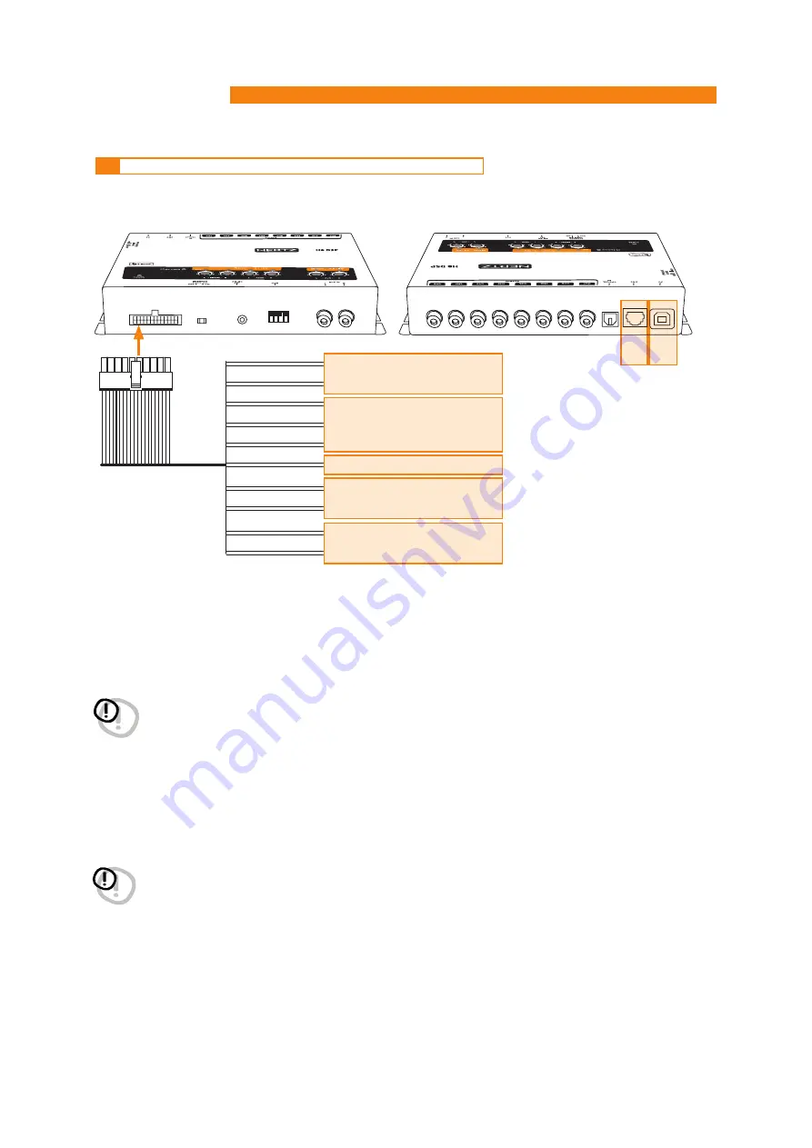
18:
Yellow
+BATT
20:
Black
-BATT
7:
Brown
OPTICAL SEL
17:
Orange
AUX SEL
6:
Pink
MEM A SEL
16:
Pink/Black
MEM B SEL
10:
Cyan
KEY MEM
5:
Red
REM IN
15:
Red
REM IN
9:
Blue
REM OUT
4
7
1.
POWER SUPPLY.
+BATT 12V:
12V Power supply positive connection terminal.
-BATT:
Power supply negative connection terminal (GND).
WARNING:
make sure the connection polarity is as indicated on the terminals. A misconnection may result in
damage to the
H8 DSP
.
After connecting to power supply, wait at least 10 seconds before turning the
H8 DSP
on.
2.
REMOTE IN-OUT.
REM IN:
input for the processor remote turn on through the source Remote Out signal.
REM OUT:
output to turn on other devices / amplifiers connected after the processor.
From the REMOTE-IN signal, the processor only takes 1 second to supply the signal to the
REM OUT
output.
The 130 mA output current capability can also drive an automotive relay (making sure it doesn’t exceed 130 mA).
WARNING:
the
H8 DSP
must be switched on before any amplifiers are turned on.
The system sources Remote Out must be connected to the product
REM IN
, and the product
REM OUT
is then to be connected to the Remote In of other devices / amplifiers.
4.4
INPUTS – REMOTE CONTROL OUTPUTS AND POWER SUPPLY


