background image

15 

Annex 


86 


15.2 

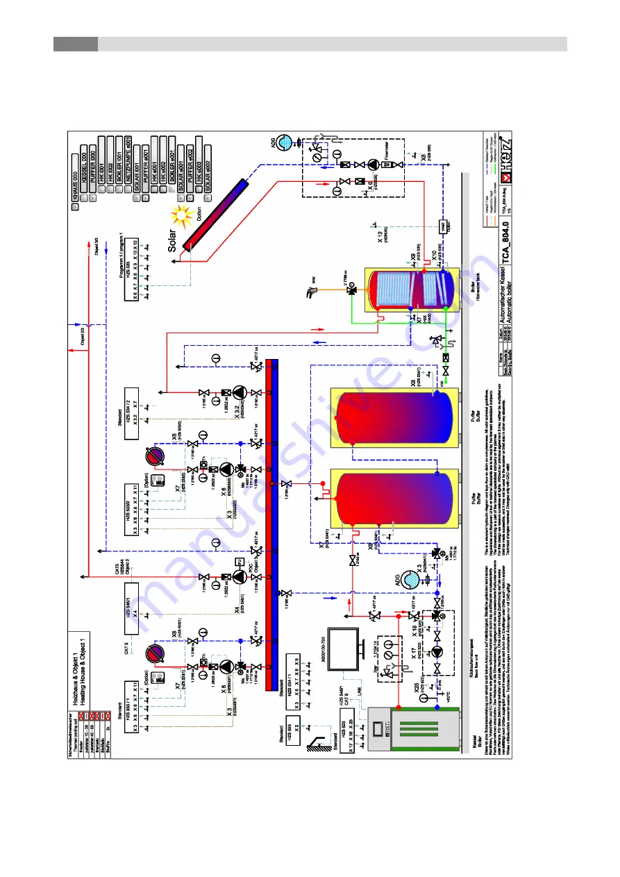
Solar module 

Program 1 


Summary of Contents for firematic PELLET 120

Page 1: ...OPERATING INSTRUCTIONS Wood chips pellets heating system firematic PELLET 120 201 ...

Page 2: ...ulic diagrams2 not recommended by HERZ are used and if a non prescribed fuel as well as pellets for non industrial use according to ENplus Swisspellet DINplus resp EN 17225 2 wood chips according to EN 17225 1 4 with specification and classes A1 A2 B1 resp G30 G50 resp log wood is used3 All business is subject to the general terms and conditions of HERZ Energietechnik GmbH as well as the agreement...

Page 3: ...Delete values 27 9 9 Fault messages and warnings 28 9 10 Modules 29 9 11 Module configuration 30 9 12 Terms and definitions 30 9 12 1 Boiler 31 9 12 2 Buffer 37 9 12 3 Hot water tank 39 9 12 4 Heating circuit 41 9 12 5 Time mode 46 9 12 6 Solar 47 9 12 7 Hydraulic compensator 49 9 12 8 Net pump 50 9 12 9 Zone valve 51 9 12 10 External requirement 53 9 12 11 Additional boiler 56 9 13 System setting...

Page 4: ... the system or opening the control unit the power supply is to be disconnected and the generally valid safety regulations are to be heeded In the boiler room no fuels may be stored outside the system It is also not permitted for objects which are not required for the purpose of operating or carrying out maintenance on the system to be kept in the boiler room When filling the fuel bunker using a pu...

Page 5: ...ng the warnings in this documentation and the instructions on the systems In unfavourable operating conditions the temperatures of parts of the housing may exceed 80 C If the door to the ash container is opened during operation the fuel supply will be shut off and the boiler will switch to the burnout phase Afterwards the boiler will switch to the operating mode HEATING OFF Ambient conditions Oper...

Page 6: ...he HERZ Customer Service department Spare parts must be obtained directly from the manufacturer or a distribution partner Due to the noise caused by the machine the customer is not exposed to health risks 2 WARNING NOTES Risk of injury and damage to property due to improper handling of the system Damage to property is possible Caution hot surface Warning against hand injuries No admittance without...

Page 7: ... in the fuel storage room must not exceed 8 of the fuel volume determined using a perforated screen with holes 5 mm in diameter Fines content at loading 1 0 m Calorific value at as delivered condition 4 6 kWh kg Bulk density BD at as delivered condition 600 kg m 4 Property class A2 only at firematic 80 301 Mechanical Strength DU EN 17831 1 at as delivered condition in m DU 97 5 97 5 Diameter 6 mm ...

Page 8: ...tion of the STL is on the left side next of the display 2 and 3 automated extinguishing device The Boiler features an automated extinguishing device The device consists of a thermal safety valve a thermostat valve 3 and a water tank 2 If the feeding screw temperature gets exceeded the valve opens independently and flushes the feeding pipe This extinguishing device is used as a safety device at bur...

Page 9: ...ces 1 Safety temperature limiter 2 Quench water container 3 Feeding pipe valve 4 Burn back protection device 5 Safety valve connection 6 Safety heat exchanger connection 7 Safety contact ash container and combustion chamber door 2 3 4 7 1 6 5 ...

Page 10: ...and storage room filling systems of HERZ would be presented the scope of this guide would be exceeded considerably More information can be provided by the company HERZ When the storage room will be filled the agitator must turn The agitator with spring discharge or articulated arm or conveyor screw assists in emptying the storage space A complete emptying of the storage space is not guaranteed by ...

Page 11: ...ring via lambda probe control A built in lambda probe which monitors continuously the flue gas content values detects fuel quality changes and ensures optimum combustion and low emission values The lambda probe controls the primary and secondary air supply and ensures a complete combustion even during minimum load 8 Speed controlled ID fan The ID fan on the backside of the boiler generates low pre...

Page 12: ...te are completely burned and the resulting ash is transported into the ash tray During the suction process the pellets are conveyed via the suction tube into a separator From the storage tank the pellets are first transported via the chute with a screw conveyor including all metal cell wheel Next the fuel is fed towards the burning chamber by the feeding screw These are then directed to the combus...

Page 13: ...to impermissible operation temperatures Back flow temperature The back flow temperature is always lower than the boiler temperature The back flow temperature must exceed 60 C as quickly as possible depending on the boiler type Temperature level retention of the back flow or the boiler temperature is achieved using a so called back flow bypass or back flow temperature monitoring In this case the fl...

Page 14: ...n even fire bed Start up phase During the start up phase the boiler operates at nominal heat output If the boiler set temperature is reached the boiler will switch to the regulation phase Regulation phase During the regulation phase the boiler is modulated between nominal load and partial load If boiler oversupplies heat i e if the boiler target temperature control hysteresis gets exceeded the boi...

Page 15: ...pass pump will switch on only if the boiler is in operating mode HEATING OFF or BURNER STOP Otherwise freezing protection disabled the boiler will start up and heat up to minimum boiler temperature 65 C Lambda control The amount of material and the rotation speed of the ID fan are controlled by the lambda control The control is able to detect marginal deviations of the fuel quality and induces a c...

Page 16: ... the boiler setting This is the minimal boiler must temperature during operation of the boiler For example If a required temperature by the consumer is lower than the minimum requirement the boiler automatically selects the minimum requirement temperature The boiler END temperature results from the boiler MUST temperature and the adjustable control hysteresis The boiler switches to the Ready mode ...

Page 17: ...e see Fig 8 2 Caution Consider the set minimum requirement Fig 8 2 Example temperature manager with buffer and without difference If the required buffer top temperature required temperature is lower than the buffer bottom MUST temperature than the required boiler temperature is the result of the required buffer bottom temperature the adjusted temp increase the adjusted difference see Fig 8 3 Cauti...

Page 18: ...e mode is applied directly on the buffer then the required buffer top temperature is set directly in the time mode module Now it must be distinguished again if the buffer top temperature is higher than the adjusted buffer bottom MUST temperature In this case the required boiler temperature is the result of the required buffer bottom MUST temperature the adjusted temp increase the adjusted differen...

Page 19: ...Temperature manager 8 19 Fig 8 6 Example temperature manager when time mode without difference ...

Page 20: ...OL 9 1 Starting the system To switch on the display two conditions must be fulfilled The boiler must be connected to the power supply see figure below The main switch 1 on the boiler front must be switched on see figure If these two conditions are fulfilled the starting process of the display which takes 1 2 minutes starts Boiler main switch only firematic 120 201 1 ...

Page 21: ... adapted individually If the following symbol is pressed the main menu will be displayed Home Button you come back one level return button fault messages warnings alarms will be displayed see chapter 10 the individual modules boiler hot water tank buffer heating circuit solar hydraulic compensator net pump zone valve external demand will be displayed the menu settings network configuration E Mail ...

Page 22: ...n whereby the remaining time only starts to run when the boiler status chimney sweeping function begins ignition phase does not count towards this After pressing the chimney sweeping symbol the boiler can also be switched off in addition to the nominal output program With the aggregate test connected components can be tested individually The symbol is only visible if the code has been entered the ...

Page 23: ...tion in the menu settings Navigation 1 Navigation 2 Screen Screen By pressing the button Note Figure Editor is displayed Enter the corresponding code see below and press OK to confirm the main menu will be displayed if you have already entered a code the control will be locked Code 111 the previous page will be displayed the open padlock icon appears ...

Page 24: ...d on if there are no errors that prevent it from starting The boiler will switch to the operating condition burn out phase except cold start or ready When switching off during cold start the cold start is ended and then changes to the burnout phase This prevents impermissibly high amount of fuel in the combustion chamber CHIMNEY SWEEPING FUNCTION Navigation Screen If chimney sweeping function is a...

Page 25: ...i e in the entered case the time and date are updated every 12 hours Can the screen be locked for 30 seconds the summer of winter time gets selected NTP Update a NTP update can be carried out The time and date will be updated immediately the main menu will be displayed i FBR If activated the language setting changes with the remote control Note NTP Network Time Protocol is used to synchronize date...

Page 26: ...ill be deleted Boiler 000 the boiler values which can be selected manually will be displayed HOT WATER TANK i000 the hot water tank values which can be selected manually will be displayed Heating circuit i002 the heating circuit values which can be selected manually will be displayed SOLAR i003 the solar values which can be selected manually will be displayed BUFFER i004 the buffer values which ca...

Page 27: ...ack flow must etc the value will be confirmed and displayed at the main menu the page previous page of the individual modules will be displayed you get to the second page of the display values of the boiler or the selected module Note The same procedure can be applied to all other modules 9 8 2 Delete values Delete all display values Delete optional display value Navigation Code entry Symbol press...

Page 28: ...ges will be displayed Note A red highlighted field represents an active fault appears in the lower left box An orange highlighted field represents a warning A yellow highlighted field represents information no fault has occurred A highlighted grey field with crossed text represents a fault or a warning which had occurred only visible in the archive An overview of all errors and its correction is s...

Page 29: ...lues menu will be displayed If several modules have been created you can navigate through the menu of the modules up or down In the Module overview by clicking on the respective module name a separate name module name can be assigned for each module To do this first press the name above Then click on the field with the current name An input window appears The desired name can be entered In the cas...

Page 30: ... times Overview Status Agg Test Barrier times Overview Status Agg Test Barrier times Ext requirement Additional boiler Overview Status Settings Barrier times Heat curve Overview Status Settings Agg Test Barrier times 9 12 Terms and definitions In this chapter all parameters and terms of the different modules are explained Some terms can be a display value and a setting value To recognize these the...

Page 31: ... the back flow temperature C Boiler power Indicates the boiler output Back flow mixer Indicates the actual state of the back flow mixer OPEN CLOSE Back flow pump Indicates the actual state of the back flow pump ON OFF Status 2 1 2 3 4 Status time The status time indicates how long the boiler has been in the current boiler status min Flue gas temperature Indicates the flue gas temperature C combust...

Page 32: ...e required boiler temperature is regulated C Waiting period The transfer of the demand to the boiler is delayed by the set time 0 240min min HEC barrier time No heat exchanger cleaning takes place in the set time 00 00 23 59 Settings 2 1 2 3 4 5 Variant 1 If weather related performance managment is not activated Power max Setting up the maximum boiler power 30 100 Enable boiler power regulation li...

Page 33: ...oad operation with the aid of the ID fan observe air correction of the lambda sensor 75 75 Mat correction part load Correction of the amount of material in part load operation by using the stoker screw observe material correction of the lambda probe 95 95 Mat correction nominal load Correction of the amount of material in nominal load operation by using the stoker screw observe material correction...

Page 34: ...input has triggered End switch room discharge Display of the status of the end switch room discharge If the control lamp is lit the end switch room discharge input has triggered Discharge Display of the status of the discharge If switch on green Output active Vacutrans flap opened Indicates the status of the vacutrans flap If switch on green Output active pellet sucker Displays the condition of th...

Page 35: ... Displays the state of the Output temperature monitoring control storage room If the indicator lamp lights up the maximum storage room temperature is exceeded the storage room temperature control sensor is active Sum annoyance Displays the condition of the Sum annoyance If switch on green Output active active fault Operating alarm unit Displays the condition of the Operating alarm unit If switch o...

Page 36: ...the set inspection interval has been exceeded standard 1000 operating hours h Maintenance interval date Display date until to next maintenance Information message Service Error No 39 appears after exceeding the set maintenance interval standard 3000 operating hours or after exceeding the annual interval Maintenance interval rest operating hours Display rest operating hours until to next maintenanc...

Page 37: ...tes the buffer bottom temperature C Switching temperature Indicates switching temperature average daytime temperature In general the switching temperature conduces to switch between winter set temperature and summer set temperature C Outside temperature Display of the actual outside temperature C Status 2 1 2 Required temperature Indicates the required temperature of the module The required temper...

Page 38: ...t temperature and summer set temperature C Temp increase Setting up the temperature increase 25 15 of the required temperature Due to heat losses a surcharge to the must temperature winter summer of the heating cicuit can be set C Balancing outside sensor Adjusting the balancing of the outside temperature 5 to 5 C Menu Aggregate Test Agg Test 1 Buffer loading pump Indicates the state of the buffer...

Page 39: ...u for the time program barrier times and circulation times will be displayed Term Description Unit Menu Status Status 1 1 Hot water tank temperature Indicates the hot water tank upper zone temperature C Hot water tank pump Indicates the state of the hot water tank pump only visible if loading valve is inactivated Hot water tank temperature bottom Indicates the hot water tank bottom zone temperatur...

Page 40: ...ights the output for controlling of the loading valve is switched Circulation pump Indicates the state of the hot water tank pump If the indicator lamp lights up the hot water tank pump is activated and the hot water tank gets charged Menu time program barrier times circulation times Time program 1 2 3 Time 1 1 3 times can be set The second and third time can be added by the Example time 1 08 00 1...

Page 41: ...r the settings will be displayed the menu for the Aggregate Test will be displayed the menu for the time program and barrier times will be displayed Display of the heating curve Display of the set times according to the time program the menu for the time program and barrier times will be displayed Display of current outside temperature in C Display of current room temperature in C the heating time...

Page 42: ...gets multiplied by 2 and added to the flow set temperature C Status 2 1 2 Switching temperature Indicates the switching temperature average daytime temperature In general the switching temperature conduces to switch between winter set temperature and summer set temperature C Heating circuit mixer Indicates the state of the heating circuit mixer OPEN CLOSE Heating circuit pump Indicates the state o...

Page 43: ...1 2 3 Switching temperature Setting up the switching temperature 10 35 That s the average daytime temperature that conducts the switching between summer mode and winter mode The higher the value of the switching temperature is set the later the changeover to summer operation is carried out C Balancing outside sensor Adjusting the balancing of the outside temperature sensor 5 5 Adjustment of the ou...

Page 44: ...mperature 20 90 of chosen heating circuit at 10 C outside temperature C Flow set temperature at adjustable outside temperature Setting up the flow temperature 25 95 of chosen heating circuit at a adjustable outside temperature C Adjustable outside temperature Setting up the outside temperature 20 0 of chosen heating circuit regarding flow must temperature C Switch off temperature Setting up the ou...

Page 45: ...ted resume drying as follows 1 25 Day of interruption resume from day 2 30 0 15 1 3 35 16 16 4 40 17 23 17 5 12 45 24 28 24 13 40 29 29 14 35 15 30 16 25 17 23 10 24 30 25 35 26 40 27 45 28 35 29 25 30 0 figure 9 1 Flow must temperature in dependence of the bake out days at Screed drying Flow set temperature C Bake out day ...

Page 46: ...45000 45022 weather compensated requirement via heating curve during the set time Time requirement If the boiler works only as a heat supplier no heating circuit installed the set up boiler set temperature 20 100 gets supplied during the set heating times C Min loading Indicates activates the min loading 20 58 ON OFF Outside of the hot water tank loading time the hot water tank temperature is load...

Page 47: ...ll be displayed Term Description Unit Menu Status Status 1 1 Collector flow temperature Indicates the collector flow temperature C Collector back flow temperature Indicates the collector backflow temperature C Tank 1 temperature Indicates the temperature of tank 1 e g hot water tank buffer C Tank 2 temperature Indicates the temperature of tank 2 e g hot water tank buffer only visible if program 3 ...

Page 48: ... number 3 4 5 or 6 is chosen C Menu Aggregate Test Agg Test 1 Collector pump Indicates the status of the collector pump If the indicator lamp lights up the collector pump is running Loading pump Displays the condition of the loading pump If the indicator lamp lights up the collector pump is running Switching valve OPEN Display of the state of the switching valve OPEN If the indicator lamp lights u...

Page 49: ...ator has a built in temperature sensor C Existing temperature Indicates the flow temperature of the upstream module e g boiler buffer C Required temperature Indicates the required temperature of the downstream module e g heating circuit C Pump 1 Indicates the state of pump 1 ON OFF Pump 1 is the pump in the back flow on the primary side Switchover Indicates the state of switchover ON OFF Pump 2 In...

Page 50: ...P Screen By pressing the button the Net pump status menu will be displayed the menu for the Aggregate Test will be displayed the barrier times menu will be displayed Required temperature Indicates the required temperature of the downstream module e g buffer in C Existing temperature Indicates the flow temperature of the upstream module e g buffer top in C Pump Indicates the state of the net pump T...

Page 51: ...By pressing the symbol Monday preset gets assigned to remaining weekdays 9 12 9 Zone valve Navigation ZONE VALVE Screen By pressing the button the zone valve status menu will be displayed the menu for the Aggregate Test will be displayed the barrier times menu will be displayed Required temperature Indicates the required temperature of the downstream module e g buffer in C Existing temperature Ind...

Page 52: ...s 2 1 Menu Aggregate Test Agg Test 1 Zone valve OPEN Indicates the state of the zone valve If the indicator lamp lights up the zone valve is opened Menu Barrier times Barrier times 1 Time 1 1 2 times can be set The second time can be added by the Example time 1 08 00 10 00 time 2 15 00 21 00 08 00 11 00 Setting up individual buffer tank loading times of every weekday when it will be not heated By ...

Page 53: ...the settings will be displayed the menu for the requirement curve will be displayed the barrier times menu will be displayed External requirement Indicates a digital input signal of the external control loop requirement If the indicator lamp lights up the external control loop sends a requirement to the digital input Term Description Unit Menu Status Status 1 1 Demand active Indicates the state of...

Page 54: ...r times 1 Time 1 1 2 times can be set The second time can be added by the Example time 1 08 00 10 00 time 2 15 00 21 00 08 00 11 00 Setting up individual buffer tank loading times of every weekday when it will be not heated By pressing the symbol Monday preset gets assigned to remaining weekdays ...

Page 55: ...s registered at the heat supplier provided that the digital requirement external must temperature is not higher figure 9 2 Analogue set temperature as a function of the applied current signal of the external requirement At the input of the external requirement module a current signal between 4 and 20 mA should be given because a current signal is compared to a voltage signal insensitive to electro...

Page 56: ... 1 1 Boiler temperature Indicates the boiler temperature 40 80 C Flue gas temperature Indicates the flue gas temperature C Pump Indicates the state of the back flow pump ON OFF Release additional boiler Indicates the state of the release of the additional boiler ON OFF Automatic Release ON OFF Manual additional boiler active inactive Menu Settings Settings 1 Waiting period Automatic waiting time f...

Page 57: ... Indicates the state of the release of the additional boiler If the indicator lamp lights up the additional boiler is operating Menu Barrier times Barrier times 1 Time 1 1 2 times can be set The second time can be added by the Example time 1 08 00 10 00 time 2 15 00 21 00 08 00 11 00 Setting up individual buffer tank loading times of every weekday when it will be not heated By pressing the symbol ...

Page 58: ... will be displayed the screensaver settings will be displayed messages by E mail can be send Display if a USB stick is plugged in USB symbol Backup of USB stick create or play backup software by pressing the field the Modbus settings will be displayed Service special Alarm Modul external Modul necessary see user manual Alarm Modul you get to the cascade overview see Operating Instructions for casc...

Page 59: ...gle it is public and free That can be an alternative to the internet provider s server DNS 2 DNS Server of the internet provider Gateway Address the gateway address can be set up the settings can be saved the submenu for the DNS settings will be displayed connectings test The network connection can be tested Network connection ok Internet connection of the controller is ok DNS fault no or incorrec...

Page 60: ...for Modbus TCP Timeout Setting up the time delay of the data transfer RX TX Buffer Setting up the buffer size in byte max values Setting up the maximum values of the servers Accept Changes Save changes the network configuration page will be displayed again Note Modbus is an application protocol to exchange messages between intelligent Modbus controllers in the building management system The Modbus...

Page 61: ...reen Note There is a separate manual MyHerz MyHerz in which the settings are described The Remote function is used for setting the remote maintenance of the system You can choose between VNC WEB or FTP remote maintenance On the factory side the VNC remote maintenance is activated with the associated password In order to use the Internet portal www myherz at the VNC Server VNC Repeater and FTP Serv...

Page 62: ... RECEIVER LIST Navigation 1 Navigation 2 Receiver list Screen Screen By pressing the button By pressing the button receiver list a mail recipient can be added Enter your email address the receiver s E mail addresses can be set up E Mail subject The E mail subject can be set up E Mail dispatch can be activated clear the selected E mail address gets deleted off the receiver list to return to the set...

Page 63: ...itted 4 If the box is checked information will be transmitted ENTER MAIL SUBJECT TEST MAIL SENDING Navigation Subject Navigation Screen Screen By pressing the button By pressing the button the entry will be confirmed Test mail send Send E mail to recipient only visible possible if sending is active the last character will be deleted the mail server settings will be displayed characters will be wri...

Page 64: ...rmation according to capture 10 the boiler has to have a valid E mail address After the successful creation of an E mail address you can set up the exemplified values shown in the figure Look up the data of the mail server and the port number at your provider for example GMX After successful configuration of the mail server settings the boiler will send E mail with the set up values 9 13 8 E Mail ...

Page 65: ...e Navigation Screen By pressing the button Cascade overview Cascade overview shows every cascade user and its actual status and operating hours within the cascade the cascade status menu will be displayed the menu for the cascade settings will be displayed the cascade network menu will be displayed After start up the picture will appear In the centre of the screen important values according the bo...

Page 66: ...ayed in order of their occurrence 010 020 030 040 050 060 070 080 090 130 180 250 001 011 021 031 041 051 061 071 081 091 181 251 002 012 022 032 042 062 082 092 182 252 003 013 023 033 043 053 063 073 083 093 133 253 004 014 024 034 044 054 064 084 104 254 005 015 025 045 055 065 085 095 125 006 016 026 036 046 056 066 076 086 096 007 017 027 037 047 057 067 077 087 097 008 018 028 038 048 058 06...

Page 67: ...eck plug replace as necessary Check wiring incl connections replace as necessary contracting party 005 STOKER SENSOR Failure feeding screw temperature sensor Check sensor replace as necessary Check plug replace as necessary Check wiring incl connections replace as necessary contracting party 006 BURNING ROOM MAX combustion chamber temperature over adjusted combustion chamber temperature max faulty...

Page 68: ...e sensor Check sensor replace as necessary Check plug replace as necessary Check wiring incl connections replace as necessary contracting party 013 HC FLOW SENSOR Failure heating circuit flow temperature sensor Check sensor replace as necessary Check plug replace as necessary Check wiring incl connections replace as necessary contracting party 014 HC BACK FLOW SENSOR Failure heating circuit back f...

Page 69: ... Check wiring incl connections replace as necessary contracting party 021 SENSOR SOLAR TANK 2 Failure solar tank temperature sensor hot water tank buffer Check sensor replace as necessary Check plug replace as necessary Check wiring incl connections replace as necessary contracting party 022 SENSOR SOLAR RES Failure reserve solar sensor Check sensor replace as necessary Check plug replace as neces...

Page 70: ...TANK LOADING Hot water tank didn t reach set temperature during loading time hot water tank loading gets blocked till fault correction Adapt loading time Activate hot water tank priority Hot water tank settings min must 038 Inspection when exceeding the set inspection interval Conduct maintenance according to maintenance schedule Fault has to be receipted manually inspection intervals RESET 039 SE...

Page 71: ...ours Function check mixer with mixer motor Function check pump Check sensor position 056 SCREED BAKE OUT Set flow temperature does not reach the desired flow setpoint temperature for 3 hours Function check mixer with mixer motor Function check pump Check sensor position Required heat output to high 057 CHECK DATA MODUL Module parameter is not in the specified range Restart T Control Check boiler p...

Page 72: ...fire brigade in case of fire 069 STL Boiler temperature has exceeded the maximum permissible boiler temperature Cool down boiler 75 C Quit STL 070 LAMBDA FUEL when Lambda material correction is at upper or lower limit 30 minutes 071 LAMBDA FUEL if lambda probe value does not change contracting party 073 LAMBDA CALIBRATION if calibration out of range or if other error occurs during calibration and ...

Page 73: ...ON VALVE Empty level container at compact container Check vacutrans damper Check end switch vacutrans damper contracting party 087 ASH CONTAINER Ash container door is opened Connect ash container Close ash container door 090 COMB ROOM SENSOR Burning chamber door end switch active burning chamber door is open Close burning chamber door 091 WARNING ASH DISCHARGE Ash discharge did not clean respectiv...

Page 74: ...e monitoring fault contracting party 251 AUTOREBOOT 50 Software monitoring fault contracting party 252 AUTOREBOOT 51 Software monitoring fault FORMAT USB STICK via T Control if it does not work the USB stick is defective contracting party 253 AUTOREBOOT 67 Software monitoring fault contracting party 254 AUTOREBOOT 68 Software monitoring fault contracting party 10 1 Not indicated faults Fault Cause...

Page 75: ... damages and wear Repair discovered faults immediately Extinguisher container Check extinguisher container filling level and refill if necessary If re filling occurs frequently contact your contracting party 11 2 Monthly inspection Item Procedure Pivoting und step grate Burning chamber firematic 120 201 Demount cover and open burning chamber door 1 Check burning chamber stones and walls visually f...

Page 76: ...ning chamber door 1 or remove ash container cover 2 Check fault recognition and fault report Check if fault report e g ASH CONTAINER FAULT is shown ID fan Function test of ID fan using the aggregate test Check ID Fan for abnormal or conspicuous running noises Thermal safety device Check thermal safety valve tightness Safety valve Check safety valve tightness System pressure Check system pressure M...

Page 77: ...rew revision cover Clean sensors on the inside of the intermediate hopper with soft tissue on the left and right Ash storage Ash has to be stored in a non flammable air tight container till disposal Boiler room Remove flammable materials except wood chips or pellets stored in a appropriate container from the operating room Fire protection Check structural fire protection and fire doors e g self lo...

Page 78: ... remove heat exchanger insulation cover Remove deposit and check heat exchanger visually for damages and wear Remove lower rear panel 3 Remove the rear cover of the heat exchanger 4 Remove deposit at turbulator holder visually for damages and wear Conduct function test of heat exchanger using the aggregate test 5 4 3 1 2 ...

Page 79: ... by authorised personnel Drives and motors Demount intermediate hopper covers Check gear motor for abnormal or conspicuous running noises by using the aggregate test Check gear motor visually for damages and wear Item Procedure Flange bearing from firematic 130 Check visually for wear Lubricate the chain and the bearing at the outside retighten worm screw Burn back protection device Demount interm...

Page 80: ...possible adjust BFP flap Conduct paper strip test at different positions ID fan Unscrew 4x wing nut Remove and clean ID fan witch a brush 11 5 As needed Item Procedure Chimney Maintenance respectively Cleaning and inspection according to national standards Fuel storage room Fuel storage room emptying at least after 3 fillings and check visually for damages and wear e g stones damaged walls If the ...

Page 81: ... If the installation or commissioning a connection to other machines or changes of the technical specification were not carried out in accordance with regulations this declaration loses its validity We declare herewith that the above described machine the above described product complies with the corresponding regulations of the following EC EU Directives The conformity is verified by the complete...

Page 82: ... 80 40 20 500 200 firematic 120 Wood chips 80 40 20 500 200 firematic 149 Pellets 80 40 20 500 200 firematic 149 Wood chips 80 40 20 500 200 firematic 151 Pellets 80 40 20 500 200 firematic 151 Wood chips 80 40 20 500 200 firematic 180 Pellets 80 40 20 500 200 firematic 180 Wood chips 80 40 20 500 200 firematic 199 Pellets 80 40 20 500 200 firematic 201 Pellets 80 40 20 500 200 ...

Page 83: ...tenance 5 S Safety devices Burn back safety unit 8 Safety temperature limiter 8 Safety valve 8 Safety notes Basic safety information 5 Installation 5 Maintenance 6 Operation 5 Safety notes 4 Screed drying 44 T Table of content 3 T CONTROL Cascade 65 Code entry 23 Date and time 25 E Mail status report 64 Fault messages and warnings 28 Mail Server settings 64 Main menu values 26 Modbus settings 60 N...

Page 84: ...15 Annex 84 15 ANNEX 15 1 Additional boiler module Hydraulic recommendation 1 ...

Page 85: ...Annex 15 85 Hydraulic recommendation 2 ...

Page 86: ...15 Annex 86 15 2 Solar module Program 1 ...

Page 87: ...Annex 15 87 Program 2 ...

Page 88: ...15 Annex 88 Program 3 ...

Page 89: ...Annex 15 89 Program 4 ...

Page 90: ...15 Annex 90 Program 5 ...

Page 91: ...Annex 15 91 Program 6 ...

Page 92: ...16 Notes 92 16 NOTES ...

Page 93: ...Notes 16 93 ...

Page 94: ... V 1 0 HERZ Energietechnik GmbH Herzstraße 1 7423 Pinkafeld 43 3357 42 84 0 0 43 3357 42 84 0 190 office energie herz eu Deutschland Germany Herz Armaturen GmbH Fabrikstraße 76 D 71522 Backnang 49 7191 9021 0 49 7191 9021 79 verkauf herz armaturen de ...

Reviews: