background image

3

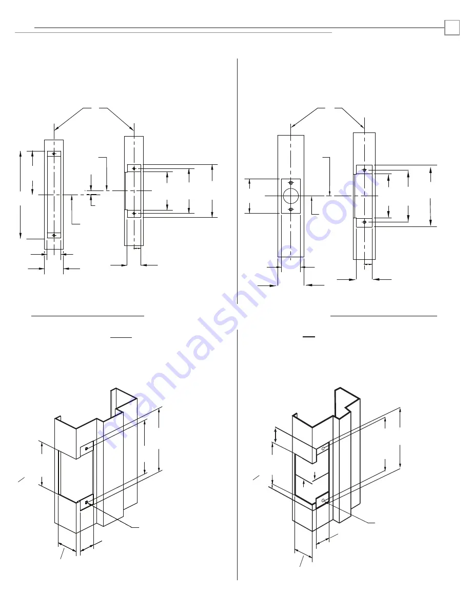
METAL JAMB DIMENSIONS FOR FACEPLATES

2 X 12-24

UNC THREADS

2 X 12-24

UNC THREADS

1-1/4"

1

-1/4"

5/32”

4-7/8"

[123.83 mm]

4-1/8"

[104.77 mm]

[85.72 mm]

3-3/8"

[31.8 mm]

[85.72 mm]

3-3/8" 

[31.8 mm]

4-1/8"

[104.77 mm]

4-7/8"

[123.83 mm]

CL

CL

29/32”

[23.01 mm]

19/32”

[15.08 mm]

Normally Used With Mortise Locks Without Deadbolt

NOTE1:

  Cannot be used with  Schlage L9000 or Yale 8700 series.

NOTE2:  Add 1/4” [6 mm] to this dimension when using a lip extension.

Cutout dimenstions for option faceplates (metal jamb):  1J, 1KM, 1NM

Normally Used With Mortise Locks With Deadbolt

NOTE1:

  Can be used with  Schlage L9000 or Yale 8700 series.

NOTE2:  Add 1/4” [6 mm] to this dimension when using a lip extension.

Cutout dimenstions for option faceplates (metal jamb):  1KD, 1ND, 1NTD

Inches [mm]

CYLINDRICAL LOCKSETS

MORTISE LOCKSETS

Inches [mm]

CL

Strike

Prep

3/8"

*

4"

8"

1-1/4"

1-3/4"

Vertical 

Centerline

CL

Lock

4-7/8"

4-1/8"

3-1/2"

5/8"

1-1/4"

Mortise

Lockset

CL

Strike

CL

Strike

Prep

5/8"

1-1/4"

Cylindrical 

Lock

CL

CL

STRIKE

LOCK

Vertical 

Centerline

2-1/4"

1-1/4"

1-3/4"

Please note the horizontal centerline of the electric strike in relation to 

the centerline of the mortise lockset.

Please note the horizontal centerline of the electric strike in relation to

the centerline of the cylindrical lockset.

[203.2 mm]

[101.6 mm]

[44.45 mm]

[31.8 mm]

[9.53 mm]

[15.88 mm]

[31.8 mm]

[88.9 mm] [104.77 mm] [123.83 mm]

[57.15 mm]

[31.8 mm]

[44.45 mm]

[15.88 mm]

[31.8 mm]

3-1/2"

[88.9 mm]

4-1/8"

[104.77 mm]

4-7/8"

[123.83 mm]


Preparing the Frame

1500 – 1-1/8” [28.58 mm]

1600 – 1-3/8” [34.93 mm]

1500 – 1-1/8” [28.58 mm]

1600 – 1-3/8” [34.93 mm]

*

  Can be Mortise lock and option specific.  See figures below if

    using a Schlage L9000 or Yale 8700 series.  

Inches [mm]

Inches [mm]

See Note 2

See Note 2

NOTE3:  Add 3/8” [9.5 mm] to this dimension when using a lip extension.

NOTE3:  Add 3/8” [9.5 mm] to this dimension when using a lip extension.

See Note 3

}

}

See Note 3

3086006.001 Rev 3

Please see Notes 2 & 3 for dimensions when using Lip Extensions

*

**

*

**

*

**

*

**

Summary of Contents for 1500 Series

Page 1: ...ing for the product and wiring methods shall be in accordance with the National Electrical Code ANSI NFPA 70 NOTE The above table applies to Models 1500 1500E 1600 and 1600E Input voltage 10 30 VDC Autosensing Ratings Static Strength 1 500 lbs Dynamic Impact 70 ft lbs Endurance 250 000 cycles Minimum Activation Duration 1 second 0 010A 0 009A 0 005A 0 004A ELECTRICAL RATINGS FOR 1500 1600 Solenoid...

Page 2: ...USE the pigtail marked 24 VDC Purple and Black Wires Red and Black Wires Converting the Operation Mode IMPORTANT NOTE Converting the electric strike to FAIL SAFE mode negates the unit s fire rating NOTE 1 The 1500 and 1600 Series Electric Strikes ship configured for FAIL SECURE OPERATION The steps below are provided to convert to FAIL SAFE OPERATION if desired The operation mode of the 1500E and 1...

Page 3: ...8 4 1 8 3 1 2 5 8 1 1 4 Mortise Lockset C L Strike C L Strike Prep 5 8 1 1 4 Cylindrical Lock C L C L STRIKE LOCK Vertical Centerline 2 1 4 1 1 4 1 3 4 Please note the horizontal centerline of the electric strike in relation to the centerline of the mortise lockset Please note the horizontal centerline of the electric strike in relation to the centerline of the cylindrical lockset 203 2 mm 101 6 m...

Page 4: ... For Use With Mortise locksets with up to throw latchbolt Compatible With Dorma 9500 Jackson Sargent 7700 and 8100 Schlage Yale 8700 X X 1N For Use With Mortise locksets with deadbolt for night latch function only Compatible With Accurate Baldwin Marks Omnia PDQ Schlage X 1NM For Use With Mortise locksets with deadbolt for night latch function only Compatible With Accurate Arrow Baldwin Best Corbi...

Page 5: ...c strike to open keeper STEP 1 LOOSEN the locking screw with the 5 64 Hex Wrench STEP 2 ADJUST the shim height to the desired level by turning the upper and lower set screws clockwise to raise and counterclockwise to lower STEP 3 TIGHTEN the locking screw to lock position 3086006 001 Rev 3 ...

Page 6: ...hett Entry Systems Inc an ASSA ABLOY Group company All rights reserved Reproduction in whole or in part without the express written permission of Hanchett Entry Systems Inc is prohibited HES Inc Phoenix AZ 800 626 7590 www hesinnovations com ...

Reviews: