2
Installation Directions
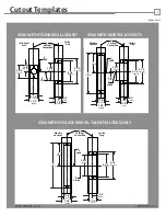
4. Prepare frame using appropriate template for
your lockset on page 4. Schlage L9000 & Yale 8700
locksets must use the template labeled “Schlage
L9000 & Yale 8700 Locks Only”. All other locksets
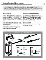
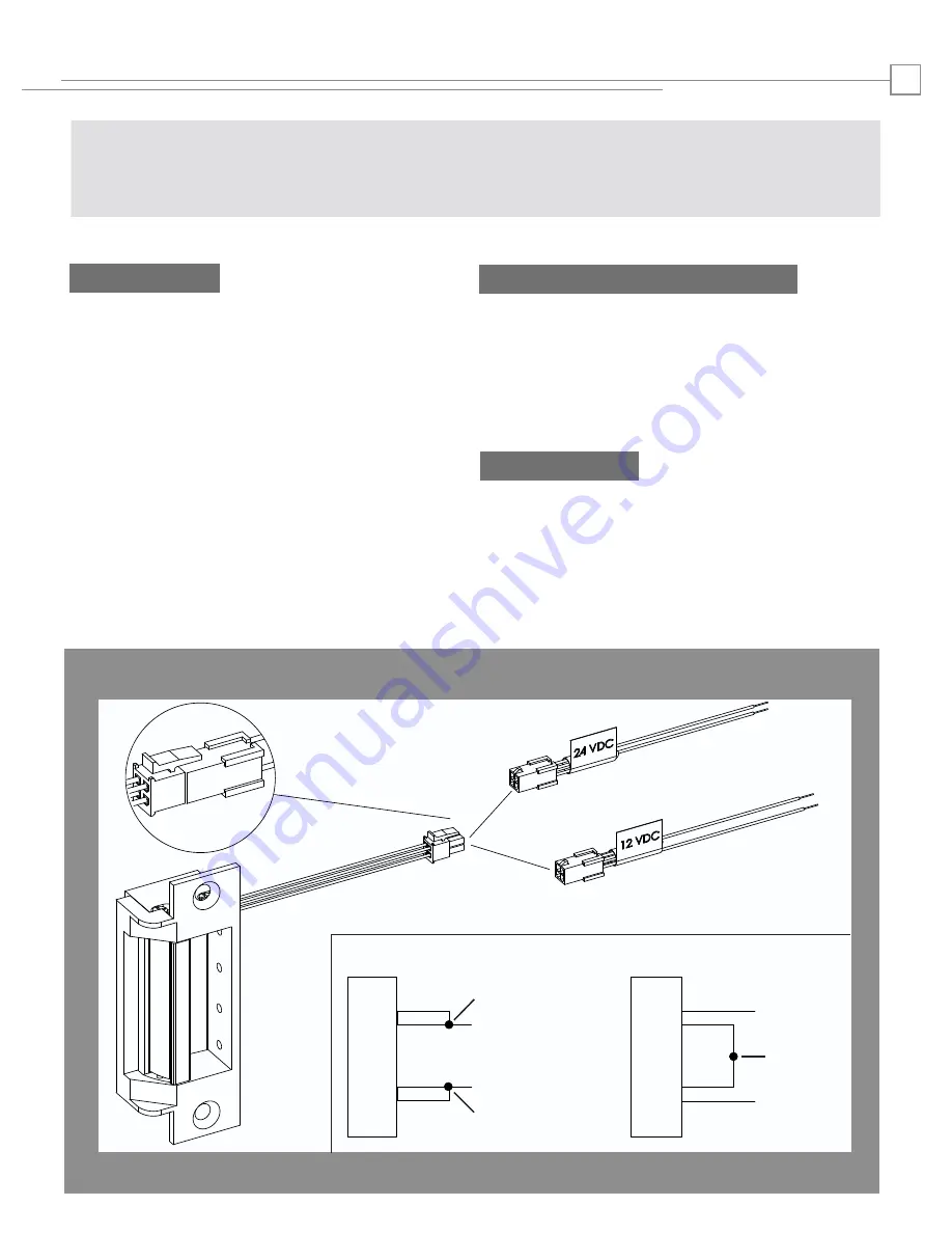
1. Select the appropriate Plug In Connector that
matches system power and electrically connect as
illustrated in Diagram 2. For 12V AC/DC or 16V AC,
the pigtail marked “12 VDC” should be used. For
24V AC/DC, the pigtail marked “24 VDC” should be
used.
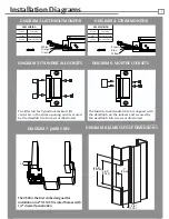
2. If using Latchbolt Monitor (LBM) or Latchbolt
Strike Monitor (LBSM), see Diagram 3 & 4 on page 3
to complete wiring.
3. The correct deadlatch or filler tab must be
installed in the strike body. See Diagram 5 & 6 on
page 3 for installation instructions.
Prepare Strike
should use the template labeled “CYLINDRICAL
LOCKSET” or “MORTISE LOCKSET”.
5. Attach the electric strike to the jamb using the
#12-24 screws provided.
Finish Installing
CAUTION! Before connecting any device at the installation site, verify input voltage using a multimeter.
Many power supplies and low voltage transformers operate at higher levels than listed. Any input voltage exceeding
10% of the solenoid rating may cause severe damage to the unit and will void the warranty.
Prepare Frame
DIAGRAM 2: 12V to 24V CONVERSION
RED
RED/GREEN
BLACK
VIOLET
RED
BLACK
VIOLET
RED/GREEN
IF CONNECTOR IS MISSING
(+ 12 VDC)
(-NEG)
(+ 24 VDC)
(-NEG)
ELECTRIC STRIKE
ELECTRIC STRIKE
CONNECT
TOGETHER
CONNECT
TOGETHER
CONNECT
TOGETHER


