4
of 8
7.
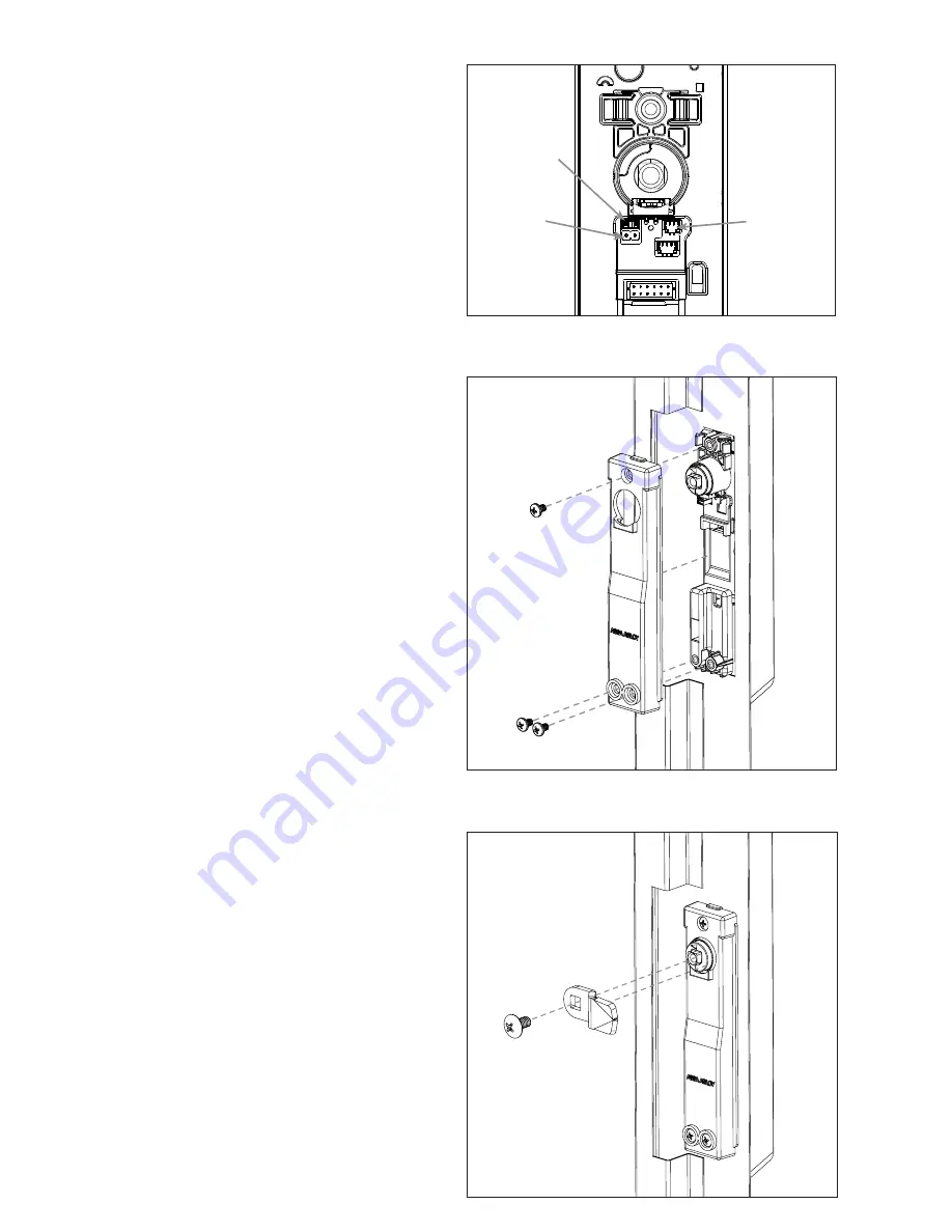
External DPS Adapter Activation.
Diagram 7.
• REMOVE the jumper on the back of
the KS200/KS210 Lock Body (A).
• CONNECT the 2-Pin Plug-In External DPS Adapter
(I) to the back of the KS200/KS10 Lock Body.
• CONNECT additional normally-open switches
as shown to monitor door/panel status in series
with the integrated Locked State monitoring.
8.
ATTACH Rear Mounting Bracket (C) to
KS200/KS210 Lock Body (A) using 3 Pan
Head Mounting Screws (E).
Diagram 8.
9.
INSTALL Locking Cam (F). Secure with
Truss Head Screw (G).
Diagram 9.
Diagram 7
DPS Activation
Diagram 8
Attach Rear Mounting Bracket (C)
with Pan Head Screws (E)
Diagram 9
Install Locking Cam (F) with Truss Head Screw (G)
External
DPS
Jumper
Connect
adapter
RS-485
120 Ohm
termination
resistor
jumper


