-
11
-
1.2
Lidar Structure
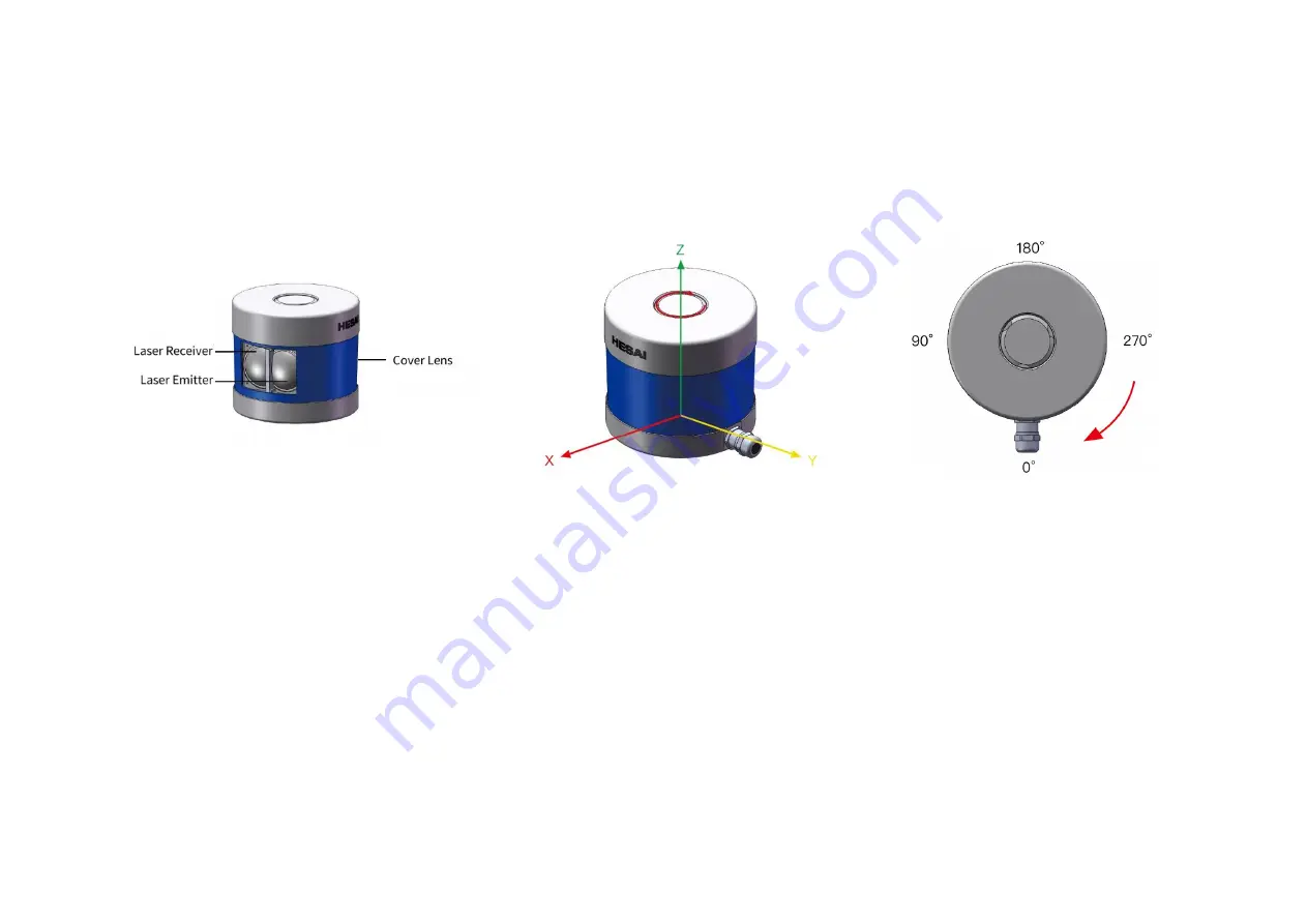
40 pairs of laser emitters and receivers are attached to a motor that rotates horizontally.
Figure 1.2 Partial Cross-Sectional Diagram
Figure 1.3 Coordinate System (Isometric View)
Figure 1.4 Rotation Direction (Top View)
The lidar's coordinate system is illustrated in Figure 1.3. Z-axis is the axis of rotation.
The origin is shown as a red dot in Figure 1.6 on the next page. All measurements are relative to the origin.
Lidar azimuthal position is defined in Figure 1.4. Y-axis corresponds to 0°.
Each laser channel has an intrinsic azimuth offset. Channel 12 is selected to define the lidar's azimuthal position.
For example, when Channel 12 passes the 90° position:
the lidar is at the 90° position;
the Azimuth field in the corresponding data block in the Point Cloud Data Packet will be 90°.
Summary of Contents for Pandar40M
Page 1: ...www hesaitech com HESAI Wechat Pandar40M 40 Channel Mechanical LiDAR User Manual...
Page 17: ...15 2 Setup 2 1 Mechanical Installation Figure 2 1 Front View Unit mm...
Page 18: ...16 Figure 2 2 Bottom View Unit mm...
Page 19: ...17 2 1 1 Quick Installation Figure 2 3 Quick Installation...
Page 20: ...18 2 1 2 Stable Installation Figure 2 4 Stable Installation...
Page 27: ...25 2 3 2 Connection Figure 2 10 Connection Box Connection with GPS...
Page 28: ...26 Figure 2 11 Connection Box Connection with PTP...


