background image

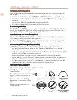
4.  Remove the liner from its packaging and place the back of the liner on the floor or countertop 

in front of the wall where it will hang.  Save the trim kit and hardware for step 10.

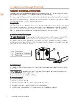
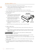
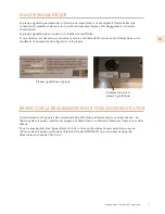
5.  With the liner on its back facing you, remove the shield(s) and blower housing(s) as follows: 

a)  Remove the shipping tape that is securing the blower shield(s) inside the liner.  

b)  Remove the shield(s) by lightly pulling it (lifting it) toward the front of the liner.  

c)  Gently close the back draft damper(s) from the top side of the liner.

d)  To remove the blower housing(s), unsnap the suitcase latches (one on each side of the 

housing).  

e)  Support the housing and lift it away from the blower base, then tip it back toward you to 

clear the blower wheel(s), and then lift it up and out from the liner.   

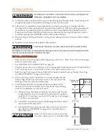
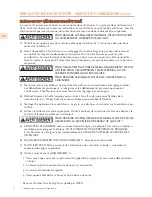
Make sure power is off at the supply panel / breaker during service or 

installation.

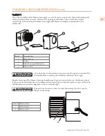
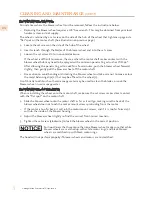
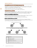
6.  One blower motor must be removed from each blower assembly to access the connection 

box(es).  The blower assembly will have a decal identifying the location of the connection 

box(es).  It is not necessary to remove the blower wheel from the motor.

a)  Remove the three screws retaining the blower motor.  

b)  Pull the motor out far enough so you can reach its electrical connector.

c)  Unplug the connector, set the blower motor and screws aside.  

•  To lighten the liner for easier handling, the remaining motor(s) can be removed as well, in the 

same manner as above.

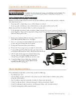
7.  WIRING PREPARATION: 

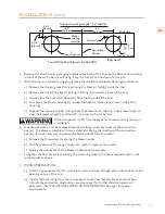
a)  Install an appropriate 1/2” UL listed electrical wire clamp through each motor box electrical 

opening on top of the liner.  

b)  Install electrical wiring from the service panel to the liner location for each motor box.  

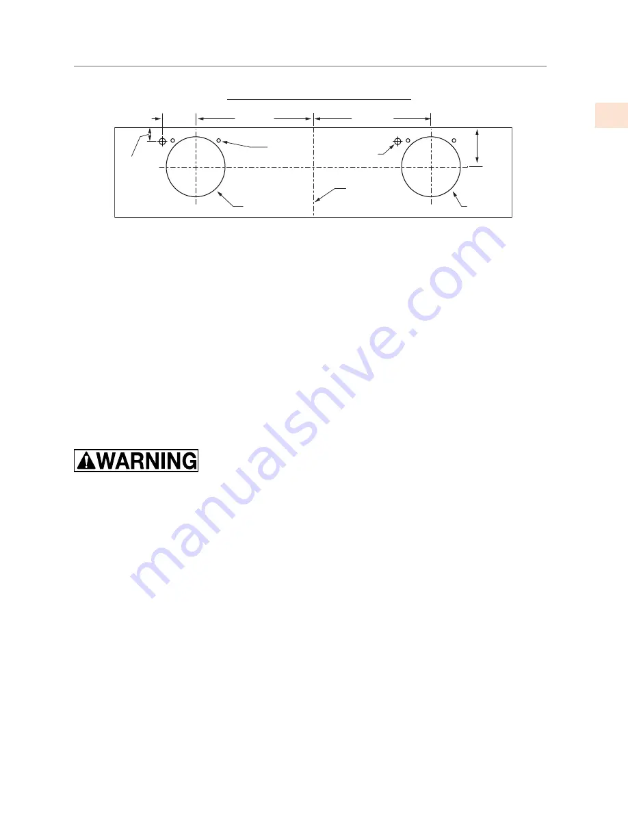
Consult the connection diagrams (on previous page) for further details on electrical 

placement.  

See “ELECTRICAL SUPPLY AND GROUNDING” on page 1 for power 

requirements.

Electrical (2

)

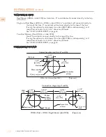
Connection diagram (48”- 54” widths)

Two WM2L Dual blowers (1200 CFM)

(Top view)

Wall side

Centerline
of liner

Motor

cooling

vent (4)

8" 

[20.3 cm] Round

5-1/2"

[14 cm]

1-3/4"

[4.4 cm]

5-1/4"

[13.3 cm]

11"

[29.9 cm]

11"

[29.9 cm]

8" 

[20.3 cm] Round

INSTALLATION 

(CONT.) 

©2019 Hestan Commercial Corporation

13

EN

Summary of Contents for KVL Series

Page 1: ...INDOOR COOKING Vent Hood Liner KVL Installation Use and Care Manual ...

Page 2: ...REFER TO THIS MANUAL FOR GUIDANCE ALL OTHER SERVICING SHOULD BE DONE BY A HESTAN AUTHORIZED SERVICE TECHNICIAN READ THESE INSTRUCTIONS CAREFULLY AND COMPLETELY BEFORE INSTALLING OR USING YOUR APPLIANCE TO REDUCE THE RISK OF FIRE BURN HAZARD OR OTHER INJURY KEEP THIS MANUAL FOR FUTURE REFERENCE SAFETY DEFINITIONS THIS INDICATES THAT DEATH OR SERIOUS INJURY MAY OCCUR AS A RESULT OF NOT OBSERVING THI...

Page 3: ...and puts it front and center in yours Thoughtfully designed and meticulously built Hestan will serve you beautifully for years to come Hestan is the only residential brand born from the dreams and demands of professional chefs From ranges to refrigeration every detail is designed to deliver the performance and reliability expected in a restaurant now available for you We appreciate you choosing He...

Page 4: ......

Page 5: ...cations when installed in a GFCI protected branch circuit TABLE OF CONTENTS 1 SAFETY PRECAUTIONS BEFORE YOU BEGIN 4 MODEL NUMBERS 4 RATING LABEL 5 REGULATORY CODE REQUIREMENTS 5 USING THE VENTILATION SYSTEM 6 CLEANING AND MAINTENANCE 9 TROUBLESHOOTING 10 DUCTING DO S AND DON TS 11 INSTALLATION 16 VENT ACCESSORIES 17 PARTS SERVICE 17 LIMITED WARRANTY When properly cared for your Hestan ventilation ...

Page 6: ...rs that may ignite Heat oils slowly on low or medium settings b Always turn hood ON when cooking at high heat or when flambéing food i e Crepes Suzette Cherries Jubilee Peppercorn Beef Flambé c Clean ventilating fans frequently Grease should not be allowed to accumulate on fan or filter d Use proper pan size Always use cookware appropriate for the size of the burner or surface element TO REDUCE TH...

Page 7: ...s examined it Install or locate this ventilation system only in accordance with the Installation section of this manual Do not cover or block any openings on this ventilation system It is highly recommended that a suitable kitchen fire extinguisher Class ABC or K be readily available and highly visible next to any cooking appliance SAFETY DURING CLEANING Clean only ventilation system parts listed ...

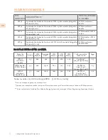
Page 8: ...tchen Ventilation System WM2L Dual WM1L Single KVL 54 54 Ventilation Liner 1200 cfm Kitchen Ventilation System Two WM2L Duals RATINGS Blower Package Amps CFM SP 0 0 Equivalent CFM CFM SP 0 1 CFM SP 0 2 CFM SP 0 3 Minimum Round Duct Size Sones WM2L Dual 2 9 600 900 531 480 430 8 50 in 2 6 5 WM2L Dual WM1L Single 4 4 900 1350 804 725 655 AKVT6810 10 79 in 2 6 3 Two WM2L Duals 5 8 1200 1800 1062 960 ...

Page 9: ...to that shown below USING THE HOOD The user can start with the a hood on the lowest setting and then increase speed and or turn on additional blowers as required Using the hood at high settings may increase heating or air conditioning requirements and costs for the house BLOWER CONTROL KNOB To operate the blower s rotate the knob through the blower speed settings by turning it clockwise facing the...

Page 10: ...s the grain or in circles BLOWER HOUSING AND SHIELD To reduce the risk of personal injury be sure the power is turned off in the hood before removing the shield s and blower housing s The blower captures grease by products in the blower housing s and blower shield s The blower shields require more frequent cleaning than the blower housing but cooking usage determines how often each item will need ...

Page 11: ...g the shield s and blower housing s Regular cleaning of the blower housing should prevent grease accumulation on the blower wheel If grease build up should occur the blower wheel may easily be cleaned in place using a soft bristle toothbrush and a common degreaser such as Formula 409 Take care not to move or lose the metal balancing clips that may be affixed to the wheel Item Description 1 Balanci...

Page 12: ... the blower wheel and take care not to move or lose the metal balancing clips 1 that may be affixed to the wheel 2 A soft bristle toothbrush with warm soapy water may be used to clean the blades or soak the blower wheel in warm soapy water BLOWER WHEEL INSTALLATION When reinstalling the wheel onto the motor shaft make sure the set screw makes direct contact with the flat spot on the motor shaft 1 ...

Page 13: ...ngs with two blowers use a white blower on the right and black on the left Make sure you have the correct motor in each housing position If the replacement blower motor includes a blower wheel then you can remove the motor and wheel together If you will re use your existing wheel then you may wish to remove the wheel before removing the motor 1 Remove the shield and blower housing as described in ...

Page 14: ...REMENTS DO S AND DON TS NEVER reduce the duct size When combining ducts together the square inch area of the outlet duct must be equal or greater than the total square inch area of the ducts being combined Only use smooth galvanized metal duct Do not use flexible or corrugated duct This type of duct will restrict airflow and reduce performance Make the duct run as short and as straight as possible...

Page 15: ... See DUCTING DO S AND DON TS on page 10 Weight and size For safe installation at least two people should be present to lift and hold the liner For larger liners it is advisable to have a third person present to assist Back Venting If venting out the wall behind the hood instead of venting through the ceiling see BACK VENTING on page 15 for details 2 When installing a Hestan hood liner it is recomm...

Page 16: ...t directly to the top of the liner If using the optional multi blower transition AKVT8812 sold separately a 12 round duct connects to it 16 1 2 above top of hood See VENT ACCESSORIES on page 16 CONNECTION DIAGRAMS Motor cooling vent Electrical WM2L Dual blower 600 CFM Top view Wall side Centerline of liner Connection diagram 30 36 width 8 20 3 cm round 5 1 2 14 cm 1 3 4 4 4 cm 5 1 4 13 3 cm 8 Roun...

Page 17: ...The blower assembly will have a decal identifying the location of the connection box es It is not necessary to remove the blower wheel from the motor a Remove the three screws retaining the blower motor b Pull the motor out far enough so you can reach its electrical connector c Unplug the connector set the blower motor and screws aside To lighten the liner for easier handling the remaining motor s...

Page 18: ... gently tap the trim pieces into place if needed 11 WIRING CONNECTION a Bring wires into each of the connection boxes and secure them with the electrical wire clamps b From inside the liner using UL listed wire nuts attach the neutral wire s to the white lead s the hot wire s to the black lead s and the ground wire s to the green lead s inside the motor box es DO NOT OPERATE HOOD WITHOUT A PROPER ...

Page 19: ...h 1200 CFM blower systems require two 8 elbows one for each 600 CFM blower unit Standard 6 15 2 cm round 8 1 2 21 6 cm Standard 8 20 3 cm round 10 3 4 27 3 cm Elbow and Transition Heights 600 CFM fan module uses 8 round 300 CFM fan module uses 6 round Drawing Not To Scale Side View 8 Round Height when fully adjusted to 90 degrees H 12 30 5 cm 6 15 2 cm 16 40 6 cm 8 Round 20 3 cm 8 1 2 21 6 cm Hood...

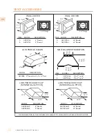
Page 20: ... AKVRC12HP 12 Round AKVWL12 12 Round WALL LOUVER A 6 A B 8 5 8 B 8 Back View 1 Flange MODEL DESCRIPTION AKVWL6 6 Round AKVWL8 8 Round WALL LOUVER B 13 B 13 A 11 A 11 Back View 1 Flange MODEL ITEM ITEM ITEM A B A B A B DESCRIPTION AKVWL10 10 Round MULTI BLOWER TRANSITION LOW PROFILE ELBOW A 17 B 16 A 10 B 12 A 23 B 30 MODEL DESCRIPTION AKVT6810 6 8 to 10 AKVT8812 8 8 to 12 12 6 16 8 Round 8 8 Round...

Page 21: ... to the original consumer purchaser of a Hestan Indoor Cooking product the Product from an HCC authorized dealer that the Product is free from defective materials or workmanship for a period of two 2 years from the date of original retail purchase or closing date for new construction whichever period is longer Limited Warranty Period HCC agrees to repair or replace at HCC s sole option any part or...

Page 22: ... electrical power or gas supply to the Product damage from alteration improper installation or improper operation of the Product damage from improper or unauthorized repair or replacement of any part or component of the Product damage from service by someone other than an authorized agent or representative of the Hestan Commercial Service Network normal wear and tear damage from exposure of the Pr...

Page 23: ...wo Year Warranty If there is any inconsistency between this Limited Warranty and any other agreement or statement included with or relating to the Product this Limited Warranty shall govern If any provision of this Limited Warranty is found invalid or unenforceable it shall be deemed modified to the minimum extent necessary to make it enforceable and the remainder of the Limited Warranty shall rem...

Page 24: ...rvice doivent être effectués par un installateur qualifié ou une agence de service NE PAS RÉPARER REMPLACER OU ENLEVER TOUTE PIÈCE DE L APPAREIL SAUF SI SPÉCIFIQUEMENT RECOMMANDÉ DANS LES MANUELS UNE INSTALLATION UN ENTRETIEN OU UNE MAINTENANCE INCORRECTS PEUT ENTRAÎNER DES BLESSURES OU DES DOMMAGES MATÉRIELS CONSULTEZ CE MANUEL DE L ORIENTATION TOUS LES AUTRES SERVICES DEVRAIENT ÊTRE EFFECTUÉS PA...

Page 25: ...ison et la met au centre de la vôtre Pensé et méticuleusement conçu Hestan vous servira magnifiquement pour les années à venir Hestan est la seule marque résidentielle née des rêves et des exigences des chefs professionnels De la cuisinière à la réfrigération chaque détail est conçu pour offrir la performance et la fiabilité attendues dans un restaurant maintenant disponible pour vous Nous appréci...

Page 26: ......

Page 27: ...au feu Lisez étape 11 CONNEXION DU CÂBLAGE à la page 16 pour plus de détails ALIMENTATION ÉLECTRIQUE ET MISE À LA TERRE Cet appareil doit être mis à la terre Lisez étape 11 CONNEXION DU CÂBLAGE à la page 16 pour plus de détails Cet appareil doit être connecté à un circuit dédié 120 VAC monophasé 60 Hz 20 ampères PROPRIÉTAIRE Demandez à l installateur de vous indiquer l emplacement du disjoncteur é...

Page 28: ... tabagisme et les débordements graisseux qui peuvent s enflammer Chauffer les huiles lentement sur les réglages bas ou moyens b Allumez toujours le hotte lorsque vous cuisinez à feu vif ou lorsque vous flambez de la nourriture c à d Crêpes Suzette cerises jubilées poivres de bœuf Flambe c Nettoyer fréquemment les ventilateurs La graisse ne doit pas s accumuler sur le ventilateur ou le filtre d Uti...

Page 29: ... correctement ou s il a été endommagé jusqu à ce qu un réparateur agréé l ait examiné Installez ou localisez ce système de ventilation uniquement conformément à la section Installation de ce manuel Ne pas couvrir ou bloquer les ouvertures de ce système de ventilation Il est fortement recommandé de disposer d un extincteur de cuisine adapté type ABC ou type K facilement disponible et très visible à...

Page 30: ...style Encastrable Intégrable de 54 po 137 2 cm WM2L ventilateurs double à deux PUISSANCE ET FLUX D AIR NOMINAL Paquet de Ventilateur Ampéres CFM SP 0 0 Équivalent CFM CFM SP 0 1 CFM SP 0 2 CFM SP 0 3 Taille minimale du conduit rond Sones WM2L ventilateurs double 2 9 600 900 531 480 430 8 po 50 po2 20 3 cm 322 6 cm2 6 5 WM2L double WM1L Unique 4 4 900 1350 804 725 655 AKVT6810 10 po 79 po2 25 4 cm ...

Page 31: ...la terre conformément aux codes locaux ou en l absence de tels codes au National Electrical Code ANSI NFPA 70 ou au Code national de l électricité du Canada CSA C22 1 La plaque signalétique donne des informations importantes sur cet appareil Hestan telles que le numéro de modèle et de série les caractéristiques électriques et les dégagements minimum d installation La plaque signalétique se trouve ...

Page 32: ...réglage le plus bas puis augmenter la vitesse et ou activer des ventilateurs supplémentaires au besoin L utilisation de la hotte à des réglages élevés peut augmenter les exigences de chauffage ou de climatisation et les coûts pour la maison BOUTON DE COMMANDE DE VENTILATEUR Pour faire fonctionner la les soufflante s faites tourner le bouton dans les réglages de vitesse du ventilateur en le tournan...

Page 33: ...les BOÎTIER ET BOUCLIER Pour réduire le risque de blessure assurez vous que l alimentation est coupée dans le hotte avant de retirer le s bouclier s et le s boîtier s du soufflante Le ventilateur capture les sous produits de la graisse dans le s boîtier s de la soufflante et le s bouclier s de la soufflante Le s bouclier s nécessitent un nettoyage plus fréquent que le boîtier du soufflante mais la...

Page 34: ...otte avant de retirer le s bouclier s et le s boîtier s du soufflantEur Un nettoyage régulier du boîtier de la soufflante devrait empêcher l accumulation de graisse sur la roue de la soufflante Si une accumulation de graisse se produit la roue de la soufflante peut facilement être nettoyée à l aide d une brosse à dents à poils doux et d un dégraissant commun tel que Formula 409 Veillez à ne pas dé...

Page 35: ...as déplacer ou perdre les clips d équilibrage métalliques qui peuvent être fixés sur la roue Une brosse à dents à poils doux et de l eau chaude savonneuse peut être utilisée pour nettoyer les lames ou faire tremper la roue de la soufflante dans de l eau chaude savonneuse INSTALLATION DE LA ROUE Lors de la réinstallation de la roue sur l arbre du moteur assurez vous que la vis de réglage est en con...

Page 36: ...irer les trois vis du support moteur qui fixent le moteur à la boîtier 3 Tirez doucement le moteur vers l avant et vers le bas 4 Débranchez le faisceau de câblage retirez l ancien moteur Pour éviter d endommager la roue de soufflante vous pouvez installer le moteur puis installer la roue sur le moteur 5 Soulevez le nouveau moteur pour pouvoir connecter le faisceau de câblage Assurez vous de bien e...

Page 37: ... po 509 7 cm en utilisant une transition multi soufflante telle que AKVT6810 optionnel Doubles à deux deux WM2L se combinent à 12 po 30 5 cm rond ou équivalent 113 po 729 cm en utilisant une transition multi soufflante telle que AKVT8812 optionnel EXIGENCES DE CANALISATION BONNE PRATIQUE DE CANALISATION NE JAMAIS réduire la taille du conduit Lors de la combinaison de conduits la surface en pouces ...

Page 38: ...coupe ou du perçage dans le mur ou le plafond ne pas endommager le câblage électrique et les autres services publics cachés d Les ventilateurs canalisés doivent toujours être ventilés vers l extérieur POUR RÉDUIRE LE RISQUE D INCENDIE UTILISEZ UNIQUEMENT DES CONDUITS MÉTALLIQUES POUR RÉDUIRE LE RISQUE D INCENDIE OU D ÉLECTROCUTION NE PAS UTILISER CE VENTILATEUR AVEC UN DISPOSITIF DE COMMANDE DE VI...

Page 39: ... s de la des sortie s d échappement Si une transition est utilisée installez le conduit de façon à ce qu il s engage à 1 po 2 54 cm de la sortie de transition b Consultez DIAGRAMMES DE CONNEXION à la page 14 pour plus de détails sur le placement de la sortie d échappement c Utilisez du utiliser du ruban HVAC métallique pas de ruban de tissu gris pour sceller tous les joints Assurez vous qu une foi...

Page 40: ...FM 7 5 16 po 18 6 cm 1 7 8 po 4 8 cm 5 1 4 po 13 3 cm 1 3 4 po 4 4 cm 7 5 16 po 18 6 cm VuedeDessus Côté du Mur Schéma de Connexion 42 po 106 7 cm de largeur Ouverture d Aération du Moteur 3 Électrique 2 5 1 2 po 14 cm Ligne centrale du Hotte 8 po 20 3 cm Rond Deux WM2L Double Soufflantes 1200 CFM 8 po 20 3 cm Rond Ouverture d Aération du Moteur 2 Électrique 2 VuedeDessus Côté du Mur 5 1 2 po 14 c...

Page 41: ...lcomanie identifiant l emplacement de la ou des boîtes de connexion Il n est pas nécessaire d enlever la roue de soufflante du moteur a Retirez les trois vis retenant le moteur de la soufflante b Tirez le moteur suffisamment loin pour pouvoir atteindre son connecteur électrique c Débrancher le connecteur mettre le moteur de la soufflante et les vis de côté Pour alléger la unité afin de faciliter s...

Page 42: ... avec les serre fils électriques b À l intérieur de la unité à l aide des écrous de câblage homologués UL fixez les fils neutres aux fils blancs les fils chauds aux fils noir et le fil de terre à la fil verte à l intérieur de la des boîte s du moteur s NE PAS UTILISER LA HOTTE SANS UNE MISE À LA TERRE APPROPRIÉE 12 Branchez le s moteur s dans la hotte et réinstallez le s moteur s de la soufflante ...

Page 43: ... 2 cm COUDES POUR 1200 CFM Les unités dotées d un système de soufflante de 1200 CFM utilisent deux coude de 8 po 20 3 cm Coude Profile Bas 8 po 20 3 cm en Rond à 6 x 8 1 2 po 15 2 x 21 6 cm Rectangle Coude Rond de 6 po H 8 1 2 po 21 6 cm Hauteur quand ajustée à 90 degrés Coude Rond de 8 po H 10 3 4 po 27 3 cm La unité de 600 CFM utilise un rond de 8 po 20 3 cm La unité de 300 CFM utilise un rond d...

Page 44: ... 12 po A B AKVRC10HP 10 po Rond 25 4 cm AKVRC12HP 12 po Rond 30 5 cm Modèle La Description AKVRC6HP 6 po Rond 15 2 cm AKVRC8HP 8 po Rond 20 3 cm Modèle La Description Les informations contenues dans ce document sont susceptibles d être modifiées à tout moment sans préavis Modèle La Description 8 po 20 3 cm en Rond à 6 x 8 1 2 po 15 2 x 21 6 cm Rectangulaire AKVBE8 AKVWL12 AKVWL6 6 po Rond 15 2 cm ...

Page 45: ... plus longue Période de garantie limitée HCC accepte de réparer ou de remplacer à sa seule discrétion tout composant ou pièce du Produit dont la défaillance est due à des vices de matières ou de fabrication pendant la Période de garantie limitée La présente Garantie limitée n est pas transférable et n est offerte à personne d autre que l acheteur initial au détail Acheteur La présente garantie lim...

Page 46: ... de main d œuvre de transport et de manutention le cas échéant étant à la charge de l Acheteur ÉLÉMENTS NON COUVERTS PAR LA PRÉSENTE GARANTIE LIMITÉE La présente Garantie limitée ne couvre pas ce qui suit excluant toute responsabilité financière de HCC tous dommages ou vices affectant tout Produit non acheté chez un revendeur agréé HCC variations de coloris dans la finition ou autres dommages esth...

Page 47: ...ENT PAR LA NÉGLIGENCE DE HCC LA PRÉSENTE GARANTIE LIMITÉE FORMULE VOTRE RECOURS EXCLUSIF Aucune déclaration ni aucun engagement verbal ou écrit de la part de qui que ce soit y compris sans s y limiter un employé représentant ou agent de HCC ne créera une garantie ni élargira en quoi que ce soit la portée de la présente Garantie limitée expresse d un an En cas de divergence entre la présente garant...

Page 48: ...HIS MANUAL FOR FUTURE REFERENCE CONSERVEZ CE MANUEL POUR UNE RÉFÉRENCE FUTURE Hestan Commercial Corporation 3375 E La Palma Ave Anaheim CA 92806 888 905 7463 2019 Hestan Commercial Corporation P N 022655 REV B ...

Reviews: