4. FUNCTIONAL DESCRIPTION
4.1. General Description
•
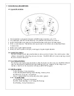
This transmitter is designed to transmit with RF-transmission duty cycle of 1%.
•
The transmitter will turn off automatically 2 seconds after all switches are released.
•
DK31/32 (ESTOP) is an emergency stop button that has priority above all other inputs.
•
DK1 is a start function. This button can be used to reset error in the receiver (Overload/ Main
Contact error).
•
DK3-18 are regular digital channels.
•
DK19-22 can be used as a 4-bit grey code trigger or regular digital channels.
4.2. Switch Error Detect
The unit contains a switch detection that detects when a switch is broken. If a switch is active when
a battery is inserted the unit will go into an error state. The RED LED will come on and stay on until
the active switch is turned off.
4.3. Low Voltage Indicator
The unit has a low battery detection function. Once the battery level becomes low the RED LED will
come on solid while the GREEN LED keeps blinking with every telegram. If the voltage level
reaches a critical level, the transmitter will only send ESTOP telegrams.
4.4. LED Description
Yellow Flashing: Unit is Operating
Yellow Flashing/Red Flashing/Green Flashing: Memory Error
Red Solid (on power up): Switch Error
(Note: Yellow LED is not visible unless the unit is opened)
4.4.1. Transmit Mode
Green Flashing: Telegram Transmitted
Red ON, Green Flashing: Low Voltage Pre Warning
Red Flashing: E-stop Transmission


