Hettich AG, Seestrasse 204a, 8806 Baech, Switzerland
Operator Manual_DancerPlus_EN_rev, 1.1
Page 20
2.3.4
When using a Vacuubrand® diaphragm pump without the PoleStar cold trap:
Fit the external vacuum sensor (Fig. 9) with the corresponding fittings so that the sensor protrudes
from above with an angle of 45° ±15°; this will prevent condensation and liquid build-ups on the
sensor. This will result in an incorrect pressure measurement.
2.3.5
When using a Vacuubrand® rotary vane pump and PoleStar cold trap:
Fit the metal tube of the DancerPlus vacuum connection to prevent liquid build-ups or siphons in
the metal tube. The outlet of the rotary vane pump contains oil particles; this is not permitted in
a cleanroom environment, i.e. the rotary vane pump must be installed outside the cleanroom. For
installation in a normal laboratory facility, we recommend extracting the rotary vane pump exhaust
air.
2.3.6
When using a Vacuubrand® rotary vane pump without the PoleStar cold trap:
The outlet of the rotary vane pump contains oil particles; this is not permitted in a cleanroom
environment, i.e. the rotary vane pump must be installed outside the cleanroom.
For installation in a normal laboratory facility, we recommend extracting the rotary vane pump
exhaust air. When solvents are evaporated with the DancerPlus, the mixture of gas, oil and air
constitutes an explosion hazard and the direct extraction of exhaust air is therefore mandatory.
Attention: The extraction may not be carried out via a normal exhaust system, as these are usually
not explosion proof; this means a special exhaust system is required.
2.3.7
Installation of the rack and shaking plate
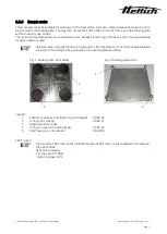
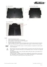
Without the FAST option, the rack is screwed to the shaking plate; this ensures that the hole for the temperature
sensor is in the rear right area. Carefully insert the rack with the shaking plate into the vacuum chamber so that
all feet of the shaking plate fully fit into the corresponding recesses in the vacuum chamber (for the magnetic
drive). Insert the temperature sensor into the corresponding hole, see Fig. 3 and Fig. 4.
With the FAST option, the shaking plate is carefully inserted into the vacuum chamber with the already fitted rack
pins (see Fig. 2) so as to ensure that all feet of the shaking plate fully fit into the corresponding recesses in the
vacuum chamber (for the magnetic drive).
The rack is now carefully lowered over and parallel to the rack pins, ensuring that the temperature
sensor hole is in the rear right area and that the rack does not tilt against the rack pins.
During the initial commissioning, the DancerPlus must not be left unattended before it has
reached a steady state.
Please be aware that the devices described here are not explosion proof (they do not fulfil
guideline VBG 24 of the German Employer’s Liability Insurance Association). Explosive mixtures
of gas and air must not be present within the immediate vicinity of the device.
Significant dust formation or aggressive vapours in the environment of the DancerPlus may lead
to debris within the device’s interior, consequently causing short
-circuiting or damage to the
electronics. Sufficient measures must therefore be taken to prevent significant dust formation and
aggressive vapours in the immediate vicinity of the device.

