4 /03.2020
INSTALLATION
Connecting the EKO-LAN modem
3
3.1
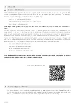
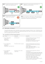
The EKO-LAN modem is designed for surface mounting. Depending on the installation substrate, a suitable mounting system should be
selected (wall plugs and screws) and the modem should be fastened using its dedicated brackets, the location of which is shown in Fig. 2.
The device requires a power supply, which can be provided in one of three ways:
-
12 V DC directly from the interfaced controller;
-
5V DC from a stabilised power supply with a micro-USB connector;
-
12 V DC from a stabilised power supply.
NOTE: Only one of the specified power supply sources shall be connected to the modem, irrespective of the units connected to this
device.
Provide an Internet over LAN connection with DHCP (dynamic IP address assignment) via an Ethernet cable with a RJ45 connector,
plugged directly into the router. If the Ethernet cable cannot be connected to the device due to technical constraints or the required
aesthetic quality, you can use the optionally available G931 RF module or use a commercially available connectivity solution, like network
repeaters, WiFi repeaters, another router with bridging, etc. See the detailed information about the G931 RF module in its manual.
The modem is Plug&Play and requires no additional configuration. A correct connection to the Internet is indicated by the green LED
flashing continuously, the orange LED flashing once every minute or once every 4 minutes (depending on the type of Ekontrol licence) and
the red LED staying off. If the LED indicators work differently, the EKO-LAN modem should first be reset as follows:
-
Disconnect the Ethernet cable for 60 seconds;
-
Disconnect the power supply from the modem;
-
Reconnect the power supply to the modem;
-
Wait 10 seconds and reconnect the Ethernet cable.
NOTE: Due to possible interference, do not lay data and Ethernet cables along high-voltage cables. Never connect the EKO-LAN
modem directly with an Ethernet cable to a PC desktop computer or a laptop.
Access point configuration instructions:
One EKO-LAN modem is sufficient to manage multiple controllers of Hewalex RES installations. You do not need another modem
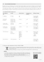
to manage more than one device. To connect multiple units, wire in parallel the data outputs A+ and B- of the EKO-LAN modem RS-
485 bus to all controllers which are to be managed. The wiring diagram for multiple devices is shown in Figure 4-6.
Connecting multiple units to the modem
3.2

