background image

1 


G422-P01 


Controller for a solar collector system 


Summary of Contents for Geco G422-P01

Page 1: ...1 G422 P01 Controller for a solar collector system...

Page 2: ...2 software version 2 00a...

Page 3: ...onnecting external devices 3 3 Using the controller 4 4 Description of control parameters 8 5 Calculating momentary power 8 6 Installation systems 9 7 Alarms 14 8 Information regarding labelling and d...

Page 4: ...and three outputs allowing for the connection of external devices pumps or three way valves depending on the selected installation type Graphic representation of input and output labelling is shown in...

Page 5: ...lled Only those sensors should be installed which are necessary for controlling the system When a sensor necessary for controlling the system is not installed or becomes damaged message reading Err wi...

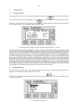
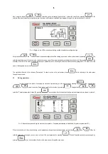
Page 6: ...eters In order to return to the main screen press twice returning to the main screen through the main menu 3 3 Editing parameters In order to select the option of changing the controller s parameters...

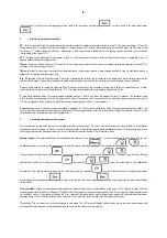
Page 7: ...ot supposed to operate in a given hour erase the white space on the time scale by pressing Pic 6 LCD screen display during while editing hours of operation for external devices The selected hour can b...

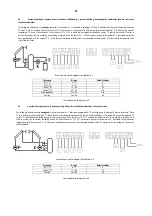
Page 8: ...right side on the screen next to the letters representing the devices Switching devices on or off is done using buttons and located on the right side of the controller Descriptions of the devices and...

Page 9: ...nute intervals Power Parameter used in installation systems described in paragraph 6 1 The controller calculates the collector power and switched off the boiler or the heater if the calculated power e...

Page 10: ...ture T4max output O2 is switched on controlling pump K When temperature T4 falls below the T4max value output O2 is switched off and the boiler is switched off Additionally controlling collector power...

Page 11: ...gy Controlling the collector pump is analogous to that in the system no 1 described in paragraph 6 1 Controlling pump C is done with the use of sensors T2 and T4 and an auxiliary control coefficient T...

Page 12: ...mming pool A If the set temperature for boiler B is achieved or T2max temperature is exceeded the controller automatically starts heating water in the swimming pool A switching off the O2 output and r...

Page 13: ...ter Range Default settings T1 C 5 15 8 T2max C 10 85 65 T4max C 10 70 65 Pump regulation Yes No Yes Cooling Yes No No List of parameters for diagram no 6 6 7 A system allowing the collectors to cooper...

Page 14: ...settings T1 C 5 15 8 T2 C 5 15 5 T2max C 10 85 65 T4max C 10 35 65 Pump regulation Yes No Yes Cooling Yes No No List of parameters for diagram no 8 6 9 A system allowing to control pumps operating wi...

Page 15: ...d When the controller reports a sensor alarm you should inspect the installation in regard to correct assembly and sensor connection 8 Information regarding labelling and disposal of worn out electric...

Reviews: