background image

15 


This option allows setting brightness and back-light time for the display. In order to change parameters: 

Press the following key combination: starting point - MAIN SCREEN: enter the 

MENU

 with 

, get to the option named 

Controller settings 

with 


, enter the 

Controller 

settings

 menu


with 

, get to the option named 

Display

 with 

, enter the 

Display

 option


with 

, choose appropriate parameters with 

 or 

, edit with 

, change values 

with 

 or 

, accept values with 

 (a continuous sound signal), return to the main screen with 


6.3  Sounds 

This options allows to switch sound signals for controller key and controller alarms on and off. In order to change parameters: Press the following key combination: starting point - 

MAIN SCREEN: enter the 

MENU

 with 

, get to the option named 

Controller settings 

with 


, enter the 

Controller settings 

menu


with 

, get to the option named 

Sounds

 with 


, enter the 

Sounds

 option


with 

, choose appropriate parameters with 

 or 

, edit with 

, change values with 

 or 

, accept values with 

 (a 

continuous sound signal), return to the main screen with 


.


6.4  Language 

This option allows you to choose one of the available language versions for the controller. In order to change language: 
Press the following key combination: starting point - MAIN SCREEN: enter the 

MENU

 with 

, get to the option named 

Controller settings 

with 


, enter the 

Controller 

settings 

menu


with 

, get to the option named 

Language

 with 


, enter the 

Language

 option


with 

, choose the appropriate language version with 

 or 

, accept 

and leave the 

Language

 option with 

 (a continuous sound signal), return to the main screen with 


Language  versions  available: 

Polish,  English,  German,  French,  Portuguese,  Spanish,  Dutch,  Italian,  Czech,  Slovak,  Romanian,  Swedish,  Norwegian,  Finnish,  Danish, 

Estonian, Lithuanian, Latvian, Slovenian, Hungarian, Croatian, Russian. 

6.5  RS485 port 

This option allows setting the parameters relating to the controller communication through monitoring. 

7.


Manual control 

This option makes it possible to manually switch all the devices in a given installation scheme on. In order to switch the devices on:  

Press the following key combination: starting point - MAIN SCREEN: enter the 

MENU

 with 

, get to the option named 

Manual control 

with 


, enter the option named 

Manual control 

with 

, chose a device to be switched on with 

 or 

, edit with 

, switch the device on with 

 or 

 (the word 

ON, 

in the case of a three-way valve

 - 

selection of servo position [

A or B

]), accept the value with 

, return to the main screen with 


ATTENTION !Exiting the Manual control option results in returning to automatic operation regardless of the settings done.  

8.


Cooling - this option is only available for flat plate solar collectors. 

This option makes it possible to cool the tap water heater by switching the solar collector pumps on in a specific time interval starting from 0.00 to the time set in the “

Stop cooling at 

[h]” 

parameter. The cooling option will be active if cooling is on (

Night cooling – Yes

) and the T2 temperature in the heater is higher or equal to the set “

Start cooling”

 temperature. 

Cooling will remain active until the heater gets cooler to the 

“Stop cooling”

 temperature or until the set time interval ends.  

When the collectors are being cooled only the P collector pump operates. All the additional devices connected to the controller are switched off.  

In order to switch cooling on: Press the following key combination: starting point - MAIN SCREEN: enter the 

MENU

 with 

, get to the option named 

Cooling 

with 


enter the option named 

Cooling

 with 

, select parameters with 

 or 

, edit 

, change values with 

 or 

, accept values with 

, return to the main screen with 


9.


Energy Statistics  

The controller has a built in module for gathering information about collectors` overheating and calculating energy generated by the collectors.  

The following data record is available in the statistics option: 

9.1.


Solar overheating

 – information about the occurrence of solar collector overheating (date and time) – the last 50 overheating events can be saved.


9.2.


Thermal energy

 – collecting and saving data on thermal energy of collectors as daily, weekly, monthly and yearly reports.


9.3.


Total energy yield

 – displaying total thermal energy computed by the controller.


9.4.


Reset total energy yield

 – resetting the total energy data (press the OK button twice to reset the counter)


9.5.


Reset energy statistics

 – resetting the statistics (thermal energy) counter (press the OK button twice to reset the counter)


9.6.


Anode operation time

 – counting the operating time of titanium anode connected to the controller. After 72 hours (time to stabilise the system) from having connected 

the controller to the mains, the controller will display the date on which it has started counting the anode operating time and saving the anode operating time in days.


The controller makes it possible to save and read energy statistics for the following time intervals:


- statistics for the last 31 days starting from the date currently set in the controller,  
- monthly statistics for the last 60 months, with possibility of reading the value for a chosen day of the month, 
- yearly statistics for the last 10 years. 

Moreover, for the daily, monthly and yearly statistics there is a possibility of graphical editing of time intervals with the use of bar diagrams.


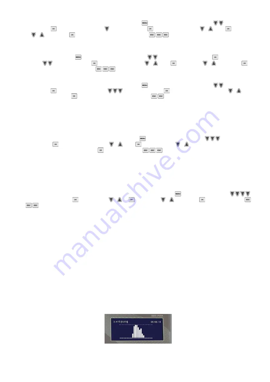
When a graphical representation of bar diagrams is being prepared, the largest value presented in a given interval appears in the left upper corner of the screen and the height of 
each bar will be scaled according to this value. Moreover, the right upper corner features date of the recording.  


Fig. 23. Graphical representation of thermal energy 

Summary of Contents for GH26-P09

Page 1: ...USER MANUAL OF AN INDEPENDENT REGULATION BLOCK GH26 P09 GH26 P09A Controller of a solar collector system applicable from version 0 1a ...

Page 2: ...t Maximum current intensity 2A O2 Transmitter output no voltage output relay Maximum current intensity 2A S1 S2 NC normally closed S2 S3 NO normally open May operate as voltage output applying voltage to S2 will result in changeover voltage output O3 230V output relay Maximum current intensity 2A O4 230V output bridging inside the controller It is allowed to bridge outside with a terminal of a rel...

Page 3: ...ch on for the blanking period set Screen blanking aims at limiting energy consumption Connect the electrical plug to the socket equipped with a protective terminal and protected with RCD It is forbidden to install pump units in close vicinity of open flames high temperatures and storage of flammable materials 3 2 Controller keyboard description The controller has a touch keyboard with 7 keys which...

Page 4: ...erence pump ON value than the T2 temperature in the lower part of the heater If the heater s temperature reaches the set value of MaxTemp T2 OFF collector s pump the P pump will be switched off Additionally in order to avoid unstable pump operation when the temperature on the sensor changes switch on and switch off hysteresis has been used Controlling the P collector pump Regulation of collector s...

Page 5: ...to boiler switch on and switch off temperatures An example of a table of resistances depending on the manufacturer of a given boiler has been presented in the table below ATTENTION The original tap water temperature sensor remains disconnected and replaced by 2 wire cable from the controller GH26 Table 2 Resistor resistance for selected boiler manufacturers Fig 5 Schematic and electrical diagram o...

Page 6: ...larly as in scheme no 1 description in point 4 1 Controlling the C circulation pump Similarly as in scheme no 2 description in point 4 2 Controlling K boiler pump The K boiler pump will be switched on if the T5 temperature at the boiler outlet gets higher by the Temperature difference ON add pump valve value than the T4 temperature in the upper part of the heater The pump will remain switched on u...

Page 7: ...he set allowable value of Max temp T4 OFF heat source Fig 9 Schematic and electrical diagram of installation no 7 4 8 Double heater system makes it possible to provide additional solar energy heating for the boiler heater with the use of a circulation return scheme no 8 Controlling the P collector pump Similarly as in scheme no 1 description in point 4 1 Controlling the C circulation pump Similarl...

Page 8: ...be found in the Parameter settings menu The C pool pump is always switched on when pool water is heated with solar collectors ATTENTION If the C pool pump is switched offwhen the solar collector pump is working and the U valve is set to the pool may damage the piping system of the pool circuit In order to protect the exchanger against lack of heat collection by the pool pump a T4 sensor should be ...

Page 9: ... scheme Controlling the C circulation pump Similarly as in scheme no 2 description in point 4 2 Fig 14 Schematic and electrical diagram of installation no 12 4 13 The system with a buffer tank used for cooperation with a central heating installation scheme no 13 Controlling the P collector pump Similarly as in scheme no 1 description in point 4 1 Controlling the C boiler pump The C boiler pump is ...

Page 10: ...ers have been used in the diagram Max temp T4 OFF heat source for heating with the use of an electrical boiler or a liquid fuel boiler and Max water temperature from boiler C for heating with the use of a fireplace or a solid fuel boiler for heating water in the upper part of the combi heater measured by the T4 sensor Fig 16 Schematic and electrical diagram of installation no 14 4 15 Tap water hea...

Page 11: ...ure in the A heater reaches Max temp T4 OFF heat source When the T4 temperature exceeds the set value the controller switches the valve back into the B heater direction and switches the P collector pump off When water is being heated in the A heater once an hour for 5 minutes the controller forces P collector pump switch off in order to check the conditions for heating the B heater and switch heat...

Page 12: ... Fig 20 Schematic and electrical diagram of installation no 18 4 19 Tap water heating system controlling solar collector pump mixing pump and system of solar energy heating for the boiler heater with the use of a circulation return scheme no 19 Controlling the P collector pump Similarly as in scheme no 1 description in point 4 1 Controlling the K mixing pump Similarly as in scheme no 7 description...

Page 13: ...option named Parameters setting with enter the Parameter settings menu with get to the option named Time program K with enter the option named Time program K with select time with or accept operation time white square or cancel operation time with accept and return a continuous sound with return to the main screen with ATTENTION Hourly setting of K are identical to those of the Time program C 5 5 ...

Page 14: ...er the flow value that results from the number of collectors in the system into the edition field Next set the required flow rate value in such a way that the Current value corresponds to the calculated value entered before The required flow can be obtained by changing the rotational speed in option Collector pump ATTENTION Leaving the field unchanged or entering wrong value does not affect the op...

Page 15: ... water heater by switching the solar collector pumps on in a specific time interval starting from 0 00 to the time set in the Stop cooling at h parameter The cooling option will be active if cooling is on Night cooling Yes and the T2 temperature in the heater is higher or equal to the set Start cooling temperature Cooling will remain active until the heater gets cooler to the Stop cooling temperat...

Page 16: ...ption of its functions has been included in point 4 for selected external devices only 10 85 C 50 C Max water temperature from boiler C A parameter only used in schemes no 14 and 18 It defines the maximum temperature of water measured by the T4 sensor for the operation of C pump cooperating with the water circuit of fireplace or solid fuel boiler 10 85 C 60 C Regulation of collector s pump P solar...

Page 17: ...the circulating pump Time of switching off the C circulation pump in a set cyclic mode according to the preset working times 1 59min 10min Table 3 Controller parameter description 13 Error alarms and controller notifications Temperature sensor error check sensors for visual condition or for proper connection to the controller The controller checks whether temperature sensors have been connected If...

Page 18: ...ing with the operation of the system and the controller Lack of required heater protection by titanium anode applies to the GH26 P09A controller only The controller is used as a power supply for the titanium anode placed in the water heater for protection of the latter against corrosion The lack of anode incorrect connection or damage to the anode circuit will switch on the sound alarm and display...

Reviews: