PAGE 18
© Copyright Hewland Engineering Limited 2001-2008
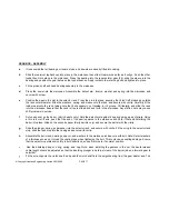
wire clip is only fitted to hold the clutch shaft in position when changing ratios. It serves no purpose when the
gearbox is fully assembled.
k
After adjusting the differential bearing preload and crownwheel backlash. Oil the taper roller bearings then load the
differential assembly in through the sideplate bore, add the sideplate and secure with nuts.
l
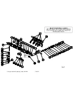
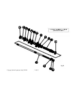
The gear cluster can be built up directly into the gearbox as described below, or built up onto fixture SK-1703.
m
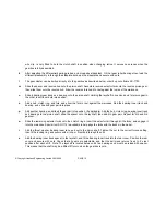
Slide the spacer and reverse hub onto the pinion shaft. Assemble reverse selector fork onto the reverse pinion gear,
then slide them onto the reverse hub. Allow the reverse fork head to rest against the inside of the maincase.
n
Slide a bearing inner track and bearing onto the pinion shaft. Holding the layshaft in one hand and 1st pinion gear in
the other, insert them both into position.
o
Add a hub, clutch ring, and fork, and allow the fork to rest against the maincase. Add the bearing inner track and
bearing, and slide 2nd gear pair into place.
p
Add
another
bearing,
and slide 6th gear pair into position, (if applicable). Add the hub, clutch ring, bearing inner track
and bearings to the pinion shaft, slide the spacer onto the layshaft, then add 5th gear pair. Repeat for 4th and 3rd
gear set.
q
Slide the remaining selector forks onto their clutch rings. Insert the selector rail through all the forks, and engage it
into the maincase. Special tool SK-1716 is available to help align the forks with the tracks in the barrel.
r
Add the thrust washer, bearing inner race, and nut to the pinion shaft. Tighten the nut to the correct torque setting,
then fit the locking ring and secure with circlip, or fit split pin through the nut.
s
Add the bearing inner track spacer to the layshaft, and fit the bearing inner track into the rear cover. Position the rear
cover and secure with nuts. Check that all gears are selectable, and that the bell crank returns freely to it’s rest
position after each shift. Note: The layshaft is located between it’s two bearings and must be preload with spacer.
This means that the shaft may be a little stiff to turn when the gearbox is cold.
Summary of Contents for FTR
Page 2: ...PAGE 2 Copyright Hewland Engineering Limited 2001 2008 This page left intentionally blank ...
Page 4: ...PAGE 4 Copyright Hewland Engineering Limited 2001 2008 This page left intentionally blank ...
Page 27: ...PAGE 27 Copyright Hewland Engineering Limited 2001 2009 6 SPEED VARIABLE PARTS ...
Page 47: ...PAGE 47 Copyright Hewland Engineering Limited 2001 2009 5 SPEED VARIABLE PARTS ...
Page 49: ...PAGE 49 Copyright Hewland Engineering Limited 2001 2009 Fig 23 BEARING CARRIER OPTIONS ...
Page 64: ...PAGE 64 Copyright Hewland Engineering Limited 2001 2008 RAMP ORIENTATION Fig 37 ...
Page 65: ...PAGE 65 Copyright Hewland Engineering Limited 2001 2009 GEARBOX TOOLING Fig 38 ...
Page 68: ...PAGE 68 Copyright Hewland Engineering Limited 2001 2008 Fig 39 ...
Page 69: ...PAGE 69 Copyright Hewland Engineering Limited 2001 2009 Fig 40 ...
Page 70: ...PAGE 70 Copyright Hewland Engineering Limited 2001 2008 Fig 41 ...
Page 71: ...PAGE 71 Copyright Hewland Engineering Limited 2001 2009 Fig 42a OUTPUT FLANGE VARIATIONS ...
Page 72: ...PAGE 72 Copyright Hewland Engineering Limited 2001 2008 Fig 42b OUTPUT FLANGE VARIATIONS ...
Page 73: ...PAGE 73 Copyright Hewland Engineering Limited 2001 2009 Fig 42c OUTPUT FLANGE VARIATIONS ...
Page 74: ...PAGE 74 Copyright Hewland Engineering Limited 2001 2008 2nd JUNE 2005 Fig 43 ...
Page 82: ...PAGE 82 Copyright Hewland Engineering Limited 2001 2008 ...
Page 83: ...PAGE 83 Copyright Hewland Engineering Limited 2001 2009 gear b o x They a r e d i ...
Page 84: ...PAGE 84 Copyright Hewland Engineering Limited 2001 2008 19th July 2004 ...
Page 85: ...PAGE 85 Copyright Hewland Engineering Limited 2001 2009 25th January 2005 Fig 47 ...


