67
Step Command Remarks
11.
Apply the QoS policy.
•
Applying the QoS policy to an
interface
•
Applying the QoS policy to VLANs
•
Applying the QoS policy globally
•
Applying the QoS policy to a
control plane
•
Applying the QoS policy to a user
profile
Choose one of the application
destinations as needed.
By default, no QoS policy is
applied.
If a QoS policy applied to a user
profile contains the action of
redirecting traffic to an
interface, make sure the
interface and the incoming
interface of packets are in the
same VLAN.
12.
(Optional.) Display traffic
redirecting configuration.
display traffic behavior user-defined
[
behavior-name
]
Available in any view.
Configuration example
Network requirements
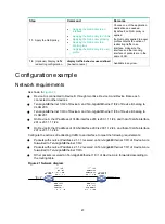
As shown in
:
•
Device A is connected to Device B through two links. Device A and Device B are each
connected to other devices.
•
Ten-GigabitEthernet 1/0/2 of Device A and Ten-GigabitEthernet 1/0/2 of Device B belong to
VLAN 200.
•
Ten-GigabitEthernet 1/0/3 of Device A and Ten-GigabitEthernet 1/0/3 of Device B belong to
VLAN 201.
•
On Device A, the IP address of VLAN-interface 200 is 200.1.1.1/24, and that of VLAN-interface
201 is 201.1.1.1/24.
•
On Device B, the IP address of VLAN-interface 200 is 200.1.1.2/24, and that of VLAN-interface
201 is 201.1.1.2/24.
Configure the actions of redirecting traffic to an interface to meet the following requirements:
•
Packets with source IP address 2.1.1.1 received on Ten-GigabitEthernet 1/0/1 of Device A are
forwarded to Ten-GigabitEthernet 1/0/2.
•
Packets with source IP address 2.1.1.2 received on Ten-GigabitEthernet 1/0/1 of Device A are
forwarded to Ten-GigabitEthernet 1/0/3.
•
Other packets received on Ten-GigabitEthernet 1/0/1 of Device A are forwarded according to
the routing table.
Figure 21 Network diagram
Summary of Contents for FlexFabric 5940 Series
Page 23: ...17 Figure 3 QoS processing flow ...
Page 84: ...78 Figure 26 MPLS label structure ...
Page 91: ...85 Switch burst mode enable ...

