background image


15 

QoS overview 

In data communications, Quality of Service (QoS) provides differentiated service guarantees for 
diversified traffic in terms of bandwidth, delay, jitter, and drop rate, all of which can affect QoS. 

QoS manages network resources and prioritizes traffic to balance system resources. 

The following section describes typical QoS service models and widely used QoS techniques. 

QoS service models 

This section describes several typical QoS service models.  

Best-effort service model 

The best-effort model is a single-service model. The best-effort model is not as reliable as other 
models and does not guarantee delay-free delivery. 

The best-effort service model is the default model for the Internet and applies to most network 
applications. It uses the First In First Out (FIFO) queuing mechanism. 

IntServ model 

The integrated service (IntServ) model is a multiple-service model that can accommodate diverse 
QoS requirements. This service model provides the most granularly differentiated QoS by identifying 
and guaranteeing definite QoS for each data flow. 

In the IntServ model, an application must request service from the network before it sends data. 
IntServ signals the service request with the RSVP. All nodes receiving the request reserve resources 
as requested and maintain state information for the application flow.  

The IntServ model demands high storage and processing capabilities because it requires all nodes 
along the transmission path to maintain resource state information for each flow. This model is 
suitable for small-sized or edge networks. However, it is not suitable for large-sized networks, for 
example, the core layer of the Internet, where billions of flows are present. 

DiffServ model 

The differentiated service (DiffServ) model is a multiple-service model that can meet diverse QoS 
requirements. It is easy to implement and extend. DiffServ does not signal the network to reserve 
resources before sending data, as IntServ does. 

QoS techniques overview 

The QoS techniques include the following features: 


Traffic classification. 


Traffic policing. 


Traffic shaping. 


Rate limit. 


Congestion management. 


Congestion avoidance.  

Summary of Contents for FlexFabric 5940 Series

Page 1: ...HPE FlexFabric 5940 Switch Series ACL and QoS Configuration Guide Part number 5200 1002b Software version Release 25xx Document version 6W102 20170830 ...

Page 2: ...tware Computer Software Documentation and Technical Data for Commercial Items are licensed to the U S Government under vendor s standard commercial license Links to third party websites take you outside the Hewlett Packard Enterprise website Hewlett Packard Enterprise has no control over and is not responsible for information outside the Hewlett Packard Enterprise website Acknowledgments Intel Ita...

Page 3: ... default action 12 Displaying and maintaining ACLs 12 ACL configuration examples 13 Interface based packet filter configuration example 13 QoS overview 15 QoS service models 15 Best effort service model 15 IntServ model 15 DiffServ model 15 QoS techniques overview 15 Deploying QoS in a network 16 QoS processing flow in a device 16 Configuring a QoS policy 18 Non MQC approach 18 MQC approach 18 Con...

Page 4: ...on management 42 Overview 42 SP queuing 42 WRR queuing 43 WFQ queuing 44 Configuration approaches and task list 44 Configuring per queue congestion management 45 Configuring SP queuing 45 Configuring WRR queuing 45 Configuring WFQ queuing 46 Configuring SP WRR queuing 46 Configuring SP WFQ queuing 47 Configuring a queue scheduling profile 48 Configuration restrictions and guidelines 49 Configurati...

Page 5: ...riority maps 74 Appendix C Introduction to packet precedence 75 IP precedence and DSCP values 75 802 1p priority 77 EXP values 77 Configuring time ranges 79 Configuration procedure 79 Displaying and maintaining time ranges 79 Time range configuration example 79 Configuring data buffers 81 Configuration task list 82 Enabling the Burst feature 82 Configuring data buffers manually 83 Setting the tota...

Page 6: ...ring congestion detection parameters 92 Displaying and maintaining QCN 93 QCN configuration examples 93 Basic QCN configuration example 93 MultiCND QCN configuration example 96 Document conventions and icons 102 Conventions 102 Network topology icons 103 Support and other resources 104 Accessing Hewlett Packard Enterprise Support 104 Accessing updates 104 Websites 105 Customer self repair 105 Remo...

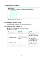
Page 7: ...destination MAC addresses 802 1p priority and link layer protocol type User defined ACLs 5000 to 5999 IPv4 and IPv6 User specified matching patterns in protocol headers Numbering and naming ACLs When creating an ACL you must assign it a number or name for identification You can specify an existing ACL by its number or name Each ACL type has a unique range of ACL numbers For an IPv4 basic or advanc...

Page 8: ... destination MAC address mask 3 Rule configured earlier A wildcard mask also called an inverse mask is a 32 bit binary number represented in dotted decimal notation In contrast to a network mask the 0 bits in a wildcard mask represent do care bits and the 1 bits represent don t care bits If the do care bits in an IP address are identical to the do care bits in an IP address criterion the IP addres...

Page 9: ...ding non first fragments Allows for matching criteria modification for efficiency For example you can configure the ACL to filter only non first fragments Configuration restrictions and guidelines When you configure ACLs follow these restrictions and guidelines Matching packets are forwarded through slow forwarding if an ACL rule contains match criteria or has functions enabled in addition to the ...

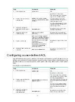
Page 10: ...ic ACLs match packets based only on source IP addresses To configure an IPv4 basic ACL Step Command Remarks 1 Enter system view system view N A 2 Create an IPv4 basic ACL and enter its view acl basic acl number name acl name match order auto config By default no ACLs exist The value range for a numbered IPv4 basic ACL is 2000 to 2999 Use the acl basic acl number command to enter the view of a numb...

Page 11: ...rmation on a VTEP 6 Optional Add or edit a rule comment rule rule id comment text By default no rule comment is configured Configuring an IPv6 basic ACL IPv6 basic ACLs match packets based only on source IP addresses To configure an IPv6 basic ACL Step Command Remarks 1 Enter system view system view N A 2 Create an IPv6 basic ACL view and enter its view acl ipv6 basic acl number name acl name matc...

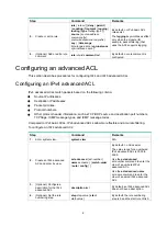
Page 12: ...col numbers Other protocol header information such as TCP UDP source and destination port numbers TCP flags ICMP message types and ICMP message codes Compared to IPv4 basic ACLs IPv4 advanced ACLs allow more flexible and accurate filtering To configure an IPv4 advanced ACL Step Command Remarks 1 Enter system view system view N A 2 Create an IPv4 advanced ACL and enter its view acl advanced acl num...

Page 13: ...in a VXLAN network the ACL matches packets as follows The ACL matches outgoing VXLAN packets by outer IPv4 header information on a VTEP The ACL matches incoming VXLAN packets by outer IPv4 header information on an intermediate transport device The ACL matches de encapsulated incoming VXLAN packets by IPv4 header information on a VTEP 6 Optional Add or edit a rule comment rule rule id comment text ...

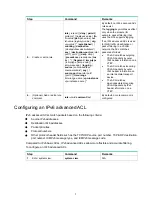
Page 14: ...ddress dest prefix any destination port operator port1 port2 dscp dscp flow label flow label value fragment icmp6 type icmp6 type icmp6 code icmp6 message logging routing type routing type hop by hop type hop type source source address source prefix source address source prefix any source port time range time range name vpn instance vpn instance name By default no IPv6 advanced ACL rules exist The...

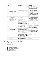
Page 15: ...ange time range name By default no Layer 2 ACL rules exist 6 Optional Add or edit a rule comment rule rule id comment text By default no rule comment is configured Configuring a user defined ACL User defined ACLs allow you to customize rules based on information in protocol headers You can define a user defined ACL to match packets A specific number of bytes after an offset relative to the specifi...

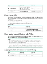
Page 16: ... copy source acl number name source acl name to dest acl number name dest acl name Configuring packet filtering with ACLs This section describes procedures for using an ACL to filter packets For example you can apply an ACL to an interface to filter incoming or outgoing packets NOTE The packet filtering feature is available on Layer 2 Ethernet interfaces Layer 2 aggregate interfaces Layer 3 Ethern...

Page 17: ...VLAN interface Step Command Remarks 1 Enter system view system view N A 2 Create a VLAN interface and enter its view interface vlan interface vlan interface id If the VLAN interface already exists you directly enter its view By default no VLAN interface exists 3 Specify the applicable scope of packet filtering on the VLAN interface packet filter filter route all By default the packet filtering fil...

Page 18: ...e number inbound outbound interface vlan interface vlan interface number inbound outbound slot slot number Display match statistics for packet filtering ACLs display packet filter statistics interface interface type interface number inbound outbound ipv6 mac user defined acl number name acl name brief Display the accumulated statistics for packet filtering ACLs display packet filter statistics sum...

Page 19: ...Create an IPv4 advanced ACL numbered 3000 Device acl advanced 3000 Configure a rule to permit access from the President s office to the financial database server Device acl ipv4 adv 3000 rule permit ip source 192 168 1 0 0 0 0 255 destination 192 168 0 100 0 Configure a rule to permit access from the Finance department to the database server during working hours Device acl ipv4 adv 3000 rule permi...

Page 20: ...econds Minimum 0ms Maximum 1ms Average 0ms Verify that a PC in the Marketing department cannot ping the database server during working hours C ping 192 168 0 100 Pinging 192 168 0 100 with 32 bytes of data Request timed out Request timed out Request timed out Request timed out Ping statistics for 192 168 0 100 Packets Sent 4 Received 0 Lost 4 100 loss Display configuration and match statistics for...

Page 21: ...anularly differentiated QoS by identifying and guaranteeing definite QoS for each data flow In the IntServ model an application must request service from the network before it sends data IntServ signals the service request with the RSVP All nodes receiving the request reserve resources as requested and maintain state information for the application flow The IntServ model demands high storage and p...

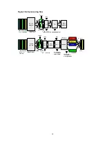
Page 22: ...inate packet drops Traffic shaping usually applies to the outgoing traffic of a port Congestion management Provides a resource scheduling policy to determine the packet forwarding sequence when congestion occurs Congestion management usually applies to the outgoing traffic of a port Congestion avoidance Monitors the network resource usage It is usually applied to the outgoing traffic of a port Whe...

Page 23: ...17 Figure 3 QoS processing flow ...

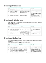
Page 24: ... traffic It is a set of class behavior associations A traffic class is a set of match criteria for identifying traffic and it uses the AND or OR operator If the operator is AND a packet must match all the criteria to match the traffic class If the operator is OR a packet matches the traffic class if it matches any of the criteria in the traffic class A traffic behavior defines a set of QoS actions...

Page 25: ...aviors exist 3 Configure an action in the traffic behavior See the subsequent chapters depending on the purpose of the traffic behavior traffic policing traffic filtering priority marking traffic accounting and so on By default no action is configured for a traffic behavior Defining a QoS policy To perform actions defined in a behavior for a class of packets associate the behavior with the class i...

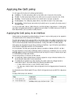
Page 26: ...peration maintenance The most common local packets include link maintenance routing LDP RSVP and SSH packets QoS policies can be applied to Layer 2 Layer 3 Ethernet interfaces Layer 3 Ethernet subinterfaces Layer 2 Layer 3 aggregate interfaces and VSI interfaces For VSI interfaces the QoS policy application feature is available in Release 2510P01 and later The term interface in this section collec...

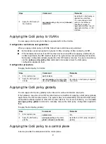
Page 27: ... remove the QoS policy configuration applied to them Configuration procedure To apply the QoS policy to VLANs Step Command Remarks 1 Enter system view system view N A 2 Apply the QoS policy to VLANs qos vlan policy policy name vlan vlan id list inbound outbound By default no QoS policy is applied to a VLAN Applying the QoS policy globally You can apply a QoS policy globally to the inbound or outbo...

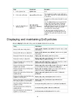
Page 28: ...figure traffic behaviors for these traffic classes as required You can use the display qos policy control plane pre defined command to display predefined control plane QoS policies Configuration restrictions and guidelines When you apply a QoS policy to a control plane follow these restrictions and guidelines If the hardware resources of IRF member device are insufficient applying a QoS policy glo...

Page 29: ... display qos acl resource slot slot number Display QoS policy configuration display qos policy user defined policy name classifier classifier name slot slot number Display information about QoS policies applied to interfaces display qos policy interface interface type interface number slot slot number inbound outbound Display information about QoS policies applied to user profiles display qos poli...

Page 30: ...nd priorities locally assigned for scheduling only Packet carried priorities include 802 1p priority DSCP precedence IP precedence and EXP These priorities have global significance and affect the forwarding priority of packets across the network For more information about these priorities see Appendixes Locally assigned priorities only have local significance They are assigned by the device only f...

Page 31: ...e following tasks Configuring an interface to trust packet priority for priority mapping Changing the port priority of an interface Configuring a priority map The device provides the following types of priority map Priority map Description dot1p dp 802 1p drop priority map dot1p exp 802 1p EXP priority map dot1p lp 802 1p local priority map dscp dot1p DSCP 802 1p priority map dscp dp DSCP drop pri...

Page 32: ...r mapping For an interface to trust a packet priority of incoming packets on an AC you must configure the interface of the AC to trust the packet priority For more information about ACs see VXLAN Configuration Guide An interface on a VXLAN IP gateway always trusts the DSCP priority in incoming packets from an AC if the packets need to be forwarded at Layer 3 If these packets need to be forwarded a...

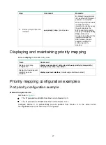
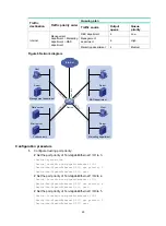
Page 33: ... maintaining priority mapping Execute display commands in any view Task Command Display priority map configuration display qos map table dot1p dp dot1p exp dot1p lp dscp dot1p dscp dp dscp dscp exp dot1p Display the trusted packet priority type on an interface display qos trust interface interface type interface number Priority mapping configuration examples Port priority configuration example Net...

Page 34: ...department connects to Ten GigabitEthernet 1 0 1 of the device which sets the 802 1p priority of traffic from the Marketing department to 3 The R D department connects to Ten GigabitEthernet 1 0 2 of the device which sets the 802 1p priority of traffic from the R D department to 4 The Management department connects to Ten GigabitEthernet 1 0 3 of the device which sets the 802 1p priority of traffi...

Page 35: ... 1 Device Ten GigabitEthernet1 0 1 qos priority 3 Device Ten GigabitEthernet1 0 1 quit Set the port priority of Ten GigabitEthernet 1 0 2 to 4 Device interface ten gigabitethernet 1 0 2 Device Ten GigabitEthernet1 0 2 qos priority 4 Device Ten GigabitEthernet1 0 2 quit Set the port priority of Ten GigabitEthernet 1 0 3 to 5 Device interface ten gigabitethernet 1 0 3 Device Ten GigabitEthernet1 0 3...

Page 36: ...dmin quit Create a QoS policy named admin and associate traffic class http with traffic behavior admin in QoS policy admin Device qos policy admin Device qospolicy admin classifier http behavior admin Device qospolicy admin quit Apply QoS policy admin to the inbound direction of Ten GigabitEthernet 1 0 3 Device interface ten gigabitethernet 1 0 3 Device Ten GigabitEthernet1 0 3 qos apply policy ad...

Page 37: ...d in QoS policy rd Device qos policy rd Device qospolicy rd classifier http behavior rd Device qospolicy rd quit Apply QoS policy rd to the inbound direction of Ten GigabitEthernet 1 0 2 Device interface ten gigabitethernet 1 0 2 Device Ten GigabitEthernet1 0 2 qos apply policy rd inbound ...

Page 38: ...nding tokens are taken away from the bucket Otherwise the traffic does not conform to the specification called excess traffic A token bucket has the following configurable parameters Mean rate at which tokens are put into the bucket which is the permitted average rate of traffic It is usually set to the committed information rate CIR Burst size or the capacity of the token bucket It is the maximum...

Page 39: ...cket C can forward PIR Rate at which tokens are put into bucket E which specifies the average packet transmission or forwarding rate allowed by bucket E EBS Size of bucket E which specifies the transient burst of traffic that bucket E can forward When a packet arrives the following rules apply If bucket C has enough tokens the packet is colored green If bucket C does not have enough tokens but buc...

Page 40: ...e evaluation result is conforming GTS GTS supports shaping the outbound traffic GTS limits the outbound traffic rate by buffering exceeding traffic You can use GTS to adapt the traffic output rate on a device to the input traffic rate of its connected device to avoid packet loss The differences between traffic policing and GTS are as follows Packets to be dropped with traffic policing are retained...

Page 41: ... Rate limit controls the rate of inbound and outbound traffic The outbound traffic is taken for example The rate limit of an interface specifies the maximum rate for forwarding packets excluding critical packets Rate limit also uses token buckets for traffic control When rate limit is configured on an interface a token bucket handles all packets to be sent through the interface for rate limiting I...

Page 42: ...es You can use the port link mode command to configure an Ethernet port as a Layer 2 or Layer 3 interface see Layer 2 LAN Switching Configuration Guide The specified CIR does not take traffic transmitted in interframe gaps into account and the actually allowed rate on an interface is greater than the specified CIR An interframe gap is a time interval for transmitting 12 bits between frames This ga...

Page 43: ...m view quit N A 8 Create a QoS policy and enter QoS policy view qos policy policy name By default no QoS policies exist 9 Associate the traffic class with the traffic behavior in the QoS policy classifier classifier name behavior behavior name insert before before classifier name By default a traffic class is not associated with a traffic behavior 10 Return to system view quit N A 11 Apply the QoS...

Page 44: ...splaying and maintaining traffic policing GTS and rate limit Execute display commands in any view Task Command Display QoS and ACL resource usage display qos acl resource slot slot number Display traffic behavior configuration display traffic behavior user defined behavior name slot slot number Display GTS configuration and statistics for interfaces display qos gts interface interface type interfa...

Page 45: ...raffic rate on Ten GigabitEthernet 1 0 2 to 10240 kbps and the excess packets are dropped Figure 11 Network diagram Configuration procedure 1 Configure Device A Configure ACL 2001 and ACL 2002 to permit the packets from the server and Host A respectively DeviceA acl basic 2001 DeviceA acl ipv4 basic 2001 rule permit source 1 1 1 1 0 DeviceA acl ipv4 basic 2001 quit DeviceA acl basic 2002 DeviceA a...

Page 46: ...ceB classifier http if match acl 3001 DeviceB classifier http quit Create a traffic class named class and configure the traffic class to match all packets DeviceB traffic classifier class DeviceB classifier class if match any DeviceB classifier class quit Create a traffic behavior named car_inbound and configure a traffic policing action CIR 20480 kbps DeviceB traffic behavior car_inbound DeviceB ...

Page 47: ...face ten gigabitethernet 1 0 1 DeviceB Ten GigabitEthernet1 0 1 qos apply policy car_inbound inbound Apply QoS policy car_outbound to the outbound direction of Ten GigabitEthernet 1 0 2 DeviceB interface ten gigabitethernet 1 0 2 DeviceB Ten GigabitEthernet1 0 2 qos apply policy car_outbound outbound ...

Page 48: ...source use efficiency Network resource memory in particular exhaustion and even system breakdown Congestion is unavoidable in switched networks and multiuser application environments To improve the service performance of your network take measures to manage and control it The key to congestion management is defining a resource dispatching policy to prioritize packets for forwarding when congestion...

Page 49: ...they are always served first Common service packets can be assigned to low priority queues to be transmitted when high priority queues are empty The disadvantage of SP queuing is that packets in the lower priority queues cannot be transmitted if packets exist in the higher priority queues In the worst case lower priority traffic might never get serviced WRR queuing WRR queuing schedules all the qu...

Page 50: ...euing All the queues are scheduled by WRR You can divide output queues to WRR priority queue group 1 and WRR priority queue group 2 Round robin queue scheduling is performed for group 1 first If group 1 is empty round robin queue scheduling is performed for group 2 On an interface enabled with group based WRR queuing you can assign queues to the SP group Queues in the SP group are scheduled with S...

Page 51: ...ring WFQ queuing Configuring SP WRR queuing Configuring SP WFQ queuing Required Configuring a queue scheduling profile Configuring per queue congestion management In per queue congestion management you manage traffic congestion on a per queue basis on ports To prevent interfaces from forwarding packets incorrectly do not batch modify the queuing configuration on these interfaces in interface range...

Page 52: ...ed on an interface 4 Assign a queue to a WFQ group and configure scheduling parameters for the queue qos wfq queue id group 1 byte count weight schedule value By default all queues on a WFQ enabled interface are in WFQ group 1 and have a weight of 1 Select byte count or weight according to the WFQ type byte count or packet based you have enabled 5 Optional Set the minimum guaranteed bandwidth for ...

Page 53: ... 1 0 1 Sysname interface ten gigabitethernet 1 0 1 Sysname Ten GigabitEthernet1 0 1 qos wrr byte count Sysname Ten GigabitEthernet1 0 1 qos wrr 4 group sp Sysname Ten GigabitEthernet1 0 1 qos wrr 5 group sp Sysname Ten GigabitEthernet1 0 1 qos wrr 6 group sp Sysname Ten GigabitEthernet1 0 1 qos wrr 7 group sp Sysname Ten GigabitEthernet1 0 1 qos wrr 0 group 1 byte count 1 Sysname Ten GigabitEthern...

Page 54: ... wfq 5 group sp Sysname Ten GigabitEthernet1 0 1 qos wfq 6 group sp Sysname Ten GigabitEthernet1 0 1 qos wfq 7 group sp Sysname Ten GigabitEthernet1 0 1 qos wfq 0 group 1 weight 1 Sysname Ten GigabitEthernet1 0 1 qos bandwidth queue 4 min 128000 Sysname Ten GigabitEthernet1 0 1 qos wfq 1 group 1 weight 2 Sysname Ten GigabitEthernet1 0 1 qos bandwidth queue 5 min 128000 Sysname Ten GigabitEthernet1...

Page 55: ...he port link mode command to configure an Ethernet port as a Layer 2 or Layer 3 interface see Layer 2 LAN Switching Configuration Guide Only one queue scheduling profile can be applied to an interface You can modify the scheduling parameters in a queue scheduling profile already applied to an interface Configuration procedure Step Command Remarks 1 Enter system view system view N A 2 Create a queu...

Page 56: ... 7 is empty the WRR group is scheduled Configuration procedure Enter system view Sysname system view Create a queue scheduling profile named qm1 Sysname qos qmprofile qm1 Sysname qmprofile qm1 Configure queue 7 to use SP queuing Sysname qmprofile qm1 queue 7 sp Assign queue 0 through queue 6 to the WRR group with their weights as 2 1 2 4 6 8 and 10 respectively Sysname qmprofile qm1 queue 0 wrr gr...

Page 57: ... display qos queue wfq interface interface type interface number Display the configuration of queue scheduling profiles display qos qmprofile configuration profile name slot slot number Display the queue scheduling profiles applied to interfaces display qos qmprofile interface interface type interface number Display queue based outgoing traffic statistics for interfaces display qos queue statistic...

Page 58: ...CP synchronization by randomly dropping packets When the sending rates of some TCP sessions slow down after their packets are dropped other TCP sessions remain at high sending rates Link bandwidth is efficiently used because TCP sessions at high sending rates always exist The RED or WRED algorithm sets an upper threshold and lower threshold for each queue and processes the packets in a queue as fo...

Page 59: ...e window size of packets This better utilizes the network resources RFC 2482 defined an end to end congestion notification mechanism named Explicit Congestion Notification ECN ECN uses the DS field in the IP header to mark the congestion status along the packet transmission path A ECN capable terminal can determine whether congestion occurs on the transmission path according to the packet contents...

Page 60: ...er the packet is sent from an ECN capable terminal The switch supports enabling ECN on a per queue basis Configuring and applying a queue based WRED table The switch supports queue based WRED tables You can configure separate drop parameters for different queues When congestion occurs packets of a queue are randomly dropped based on the drop parameters of the queue Determine the following paramete...

Page 61: ...qos wred apply table name By default no WRED table is applied to an interface and the tail drop is used on an interface Configuration example Network requirements Apply a WRED table to Ten GigabitEthernet 1 0 2 so that the packets are dropped as follows when congestion occurs For the interface to preferentially forward higher priority traffic set a lower drop probability for a queue with a greater...

Page 62: ...ability 1 Sysname wred table queue table1 queue 7 drop level 1 low limit 512 high limit 1024 discard probability 5 Sysname wred table queue table1 queue 7 drop level 2 low limit 512 high limit 1024 discard probability 10 Sysname wred table queue table1 queue 7 ecn Sysname wred table queue table1 quit Apply the queue based WRED table to Ten GigabitEthernet 1 0 2 Sysname interface ten gigabitetherne...

Page 63: ...on is configured 7 Return to system view quit N A 8 Create a QoS policy and enter QoS policy view qos policy policy name By default no QoS policies exist 9 Associate the traffic class with the traffic behavior in the QoS policy classifier classifier name behavior behavior name insert before before classifier name By default a traffic class is not associated with a traffic behavior 10 Return to sys...

Page 64: ...00 Device classifier classifier_1 quit Create a traffic behavior named behavior_1 and configure the traffic filtering action to drop packets Device traffic behavior behavior_1 Device behavior behavior_1 filter deny Device behavior behavior_1 quit Create a QoS policy named policy and associate traffic class classifier_1 with traffic behavior behavior_1 in the QoS policy Device qos policy policy Dev...

Page 65: ...r Priority marking can be used together with priority mapping For more information see Configuring priority mapping Configuration procedure To configure priority marking Step Command Remarks 1 Enter system view system view N A 2 Create a traffic class and enter traffic class view traffic classifier classifier name operator and or By default no traffic classes exist 3 Configure a match criterion if...

Page 66: ...o the incoming traffic 7 Return to system view quit N A 8 Create a QoS policy and enter QoS policy view qos policy policy name By default no QoS policies exist 9 Associate the traffic class with the traffic behavior in the QoS policy classifier classifier name behavior behavior name insert before before classifier name By default a traffic class is not associated with a traffic behavior 10 Return ...

Page 67: ...n 192 168 0 2 0 Device acl ipv4 adv 3001 quit Create advanced ACL 3002 and configure a rule to match packets with destination IP address 192 168 0 3 Device acl advanced 3002 Device acl ipv4 adv 3002 rule permit ip destination 192 168 0 3 0 Device acl ipv4 adv 3002 quit Create a traffic class named classifier_dbserver and use ACL 3000 as the match criterion in the traffic class Device traffic class...

Page 68: ...avior_mserver quit Create a traffic behavior named behavior_fserver and configure the action of setting the local precedence value to 2 Device traffic behavior behavior_fserver Device behavior behavior_fserver remark local precedence 2 Device behavior behavior_fserver quit Create a QoS policy named policy_server and associate traffic classes with traffic behaviors in the QoS policy Device qos poli...

Page 69: ...erence 4 Return to system view quit N A 5 Create a traffic behavior and enter traffic behavior view traffic behavior behavior name By default no traffic behaviors exist 6 Configure a VLAN tag adding action nest top most vlan vlan id By default no VLAN tag adding action is configured for a traffic behavior 7 Return to system view quit N A 8 Create a QoS policy and enter QoS policy view qos policy p...

Page 70: ...fic behavior test PE1 traffic behavior test PE1 behavior test nest top most vlan 100 PE1 behavior test quit Create a QoS policy named test and associate class test with behavior test in the QoS policy PE1 qos policy test PE1 qospolicy test classifier test behavior test PE1 qospolicy test quit Configure the downlink port Ten GigabitEthernet 1 0 1 as a hybrid port and assign the port to VLAN 100 as ...

Page 71: ...E1 Ten GigabitEthernet1 0 2 port link type trunk PE1 Ten GigabitEthernet1 0 2 port trunk permit vlan 100 PE1 Ten GigabitEthernet1 0 2 quit Configuring PE 2 Configure PE 2 in the same way PE 1 is configured ...

Page 72: ... behavior behavior name By default no traffic behaviors exist 6 Configure a traffic redirecting action redirect cpu interface interface type interface number By default no traffic redirecting action is configured for a traffic behavior If you execute this command multiple times the most recent configuration takes effect For traffic redirecting to an Ethernet interface on an interface module the sw...

Page 73: ... and Device B are each connected to other devices Ten GigabitEthernet 1 0 2 of Device A and Ten GigabitEthernet 1 0 2 of Device B belong to VLAN 200 Ten GigabitEthernet 1 0 3 of Device A and Ten GigabitEthernet 1 0 3 of Device B belong to VLAN 201 On Device A the IP address of VLAN interface 200 is 200 1 1 1 24 and that of VLAN interface 201 is 201 1 1 1 24 On Device B the IP address of VLAN inter...

Page 74: ...t Create a traffic behavior named behavior_1 and configure the action of redirecting traffic to Ten GigabitEthernet 1 0 2 DeviceA traffic behavior behavior_1 DeviceA behavior behavior_1 redirect interface ten gigabitethernet 1 0 2 DeviceA behavior behavior_1 quit Create a traffic behavior named behavior_2 and configure the action of redirecting traffic to Ten GigabitEthernet 1 0 3 DeviceA traffic ...

Page 75: ...nder the common or aggregate CAR This mode applies to flows that must be strictly rate limited In OR mode the traffic class can use idle bandwidth of other traffic classes associated with the hierarchical CAR This mode applies to high priority bursty traffic like video By using the two modes appropriately you can improve bandwidth efficiency For example suppose two flows exist a low priority data ...

Page 76: ...ation rate cbs committed burst size ebs excess burst size green action red action yellow action qos car car name aggregative cir committed information rate cbs committed burst size pir peak information rate ebs excess burst size green action red action yellow action By default no aggregate CAR action is configured 3 Enter traffic behavior view traffic behavior behavior name N A 4 Use the aggregate...

Page 77: ... 4 Return to system view quit N A 5 Create a traffic behavior and enter traffic behavior view traffic behavior behavior name By default no traffic behaviors exist 6 Configure an accounting action accounting byte packet By default no traffic accounting action is configured 7 Return to system view quit N A 8 Create a QoS policy and enter QoS policy view qos policy policy name By default no QoS polic...

Page 78: ...ation procedure Create basic ACL 2000 and configure a rule to match packets with source IP address 1 1 1 1 Device system view Device acl basic 2000 Device acl ipv4 basic 2000 rule permit source 1 1 1 1 0 Device acl ipv4 basic 2000 quit Create a traffic class named classifier_1 and use ACL 2000 as the match criterion in the traffic class Device traffic classifier classifier_1 Device classifier clas...

Page 79: ...ernet 1 0 1 Device Ten GigabitEthernet1 0 1 qos apply policy policy inbound Device Ten GigabitEthernet1 0 1 quit Display traffic statistics to verify the configuration Device display qos policy interface ten gigabitethernet 1 0 1 Interface Ten GigabitEthernet1 0 1 Direction Inbound Policy policy Classifier classifier_1 Operator AND Rule s If match acl 2000 Behavior behavior_1 Accounting enable 285...

Page 80: ...st out GTS Generic Traffic Shaping IntServ Integrated Service ISP Internet Service Provider MPLS Multiprotocol Label Switching PE Provider Edge PIR Peak Information Rate QoS Quality of Service RED Random Early Detection RSVP Resource Reservation Protocol SP Strict Priority ToS Type of Service VPN Virtual Private Network WFQ Weighted Fair Queuing WRED Weighted Random Early Detection WRR Weighted Ro...

Page 81: ...0 16 to 23 2 0 24 to 31 3 0 32 to 39 4 0 40 to 47 5 0 48 to 55 6 0 56 to 63 7 0 Appendix C Introduction to packet precedence IP precedence and DSCP values Figure 23 ToS and DS fields M B Z RFC 1122 IP Type of Service ToS RFC 791 Must Be Zero RFC 1349 IPv4 ToS byte 0 7 6 1 5 4 3 2 Bits Preced ence Type of Service 0 7 6 DSCP Class Selector codepoints Differentiated Services Codepoint DSCP RFC 2474 C...

Page 82: ... IP precedence IP precedence decimal IP precedence binary Description 0 000 Routine 1 001 priority 2 010 immediate 3 011 flash 4 100 flash override 5 101 critical 6 110 internet 7 111 network Table 7 DSCP values DSCP value decimal DSCP value binary Description 46 101110 ef 10 001010 af11 12 001100 af12 14 001110 af13 18 010010 af21 20 010100 af22 22 010110 af23 26 011010 af31 28 011100 af32 30 011...

Page 83: ...ows the format of the 802 1Q tag header The Priority field in the 802 1Q tag header is called 802 1p priority because its use is defined in IEEE 802 1p Table 8 shows the values for 802 1p priority Figure 25 802 1Q tag header Table 8 Description on 802 1p priority 802 1p priority decimal 802 1p priority binary Description 0 000 best effort 1 001 background 2 010 spare 3 011 excellent effort 4 100 c...

Page 84: ...78 Figure 26 MPLS label structure ...

Page 85: ... 12 absolute statements The active period of a time range is calculated as follows 1 Combining all periodic statements 2 Combining all absolute statements 3 Taking the intersection of the two statement sets as the active period of the time range Configuration procedure Step Command Remarks 1 Enter system view system view N A 2 Create or edit a time range time range time range name start time to en...

Page 86: ...A acl ipv4 basic 2001 rule permit source 192 168 1 2 0 time range work DeviceA acl ipv4 basic 2001 rule deny source any time range work DeviceA acl ipv4 basic 2001 quit Apply IPv4 basic ACL 2001 to filter outgoing packets on Ten GigabitEthernet 1 0 2 DeviceA interface ten gigabitethernet 1 0 2 DeviceA Ten GigabitEthernet1 0 2 packet filter 2001 outbound DeviceA Ten GigabitEthernet1 0 2 quit Verify...

Page 87: ...ed into queues each of which is equally divided by all the interfaces on the switch as shown in Figure 29 When congestion occurs the following rules apply a An interface first uses the relevant queues of the fixed area to store packets b When a queue is full the interface uses the corresponding queue of the shared area c When the queue in the shared area is also full the interface discards subsequ...

Page 88: ...Applying data buffer configuration Enabling the Burst feature The Burst feature enables the device to automatically allocate cell and packet resources It is well suited to the following scenarios Broadcast or multicast traffic is intensive resulting in bursts of traffic Traffic enters a device from a high speed interface and goes out of a low speed interface Traffic enters a device from multiple s...

Page 89: ...or each queue is determined by the chip based on your configuration and the number of packets to be received and sent To set the maximum shared area ratio for a queue Step Command Remarks 1 Enter system view system view N A 2 Set the maximum shared area ratio for a queue buffer egress slot slot number cell queue queue id shared ratio ratio The default setting is 33 Setting the fixed area ratio for...

Page 90: ...sk Command Display buffer size settings display buffer slot slot number queue queue id Display data buffer usage display buffer usage slot slot number Burst configuration example Network requirements As shown in Figure 30 a server connects to the switch through a 1000 Mbps Ethernet interface The server sends high volume broadcast or multicast traffic to the hosts irregularly Each host connects to ...

Page 91: ...85 Switch burst mode enable ...

Page 92: ...lue of that 802 1p priority is called a congestion notification priority value CNPV Congestion notification domain CND A set of RPs and CPs with QCN enabled for a CNPV Congestion point identifier CPID An 8 byte unique identifier for a CP in the network Quantized feedback QntzFb A 6 bit quantized feedback value indicating the extent of congestion QCN message format Data flow format An RP can add CN...

Page 93: ...bits Its value is fixed at 0 Quantized Feedback 6 bits Quantized value indicating the extent of congestion CPID 8 bytes Identifies the CP where congestion occurs cnmQoffset 2 bytes Indicates the difference between instantaneous queue size at the sampling point and desired queue length cnmQdelta 2 bytes Indicates the difference between instantaneous queue sizes at the current sampling point and at ...

Page 94: ...s The RPs also periodically probe the bandwidth and increase their transmission rates if they fail to receive CNMs for a specific period of time Figure 34 How QCN works Version Encapsulated priority cnmQDelta cnmQOffset Congestion Point Identifier CPID Quantized Feedback ReservedV Encapsulated MSDU Encapsulated MSDU length Encapsulated destination MAC address Octet Length 1 4 bits 1 2 6 bits 2 6 b...

Page 95: ...δ where w is a constant to control the weight of Qδ in determining the value of Fb The CP determines whether to generate CNMs based on the Fb value When Fb 0 no congestion occurs and the CP does not generate a CNM When Fb 0 congestion occurs and the CP generates an CNM containing the QntzFb QntzFb is the quantized value of Fb and is calculated according to the following rules If Fb Qeq x 2 x w 1 Q...

Page 96: ...hen sending out the frames Priority mapping Incoming frames with a CNPV are assigned to the corresponding output queue enabled with QCN Traffic with other priority values cannot enter that output queue Priority to queue mappings are determined by the QoS priority mapping table see Configuring priority mapping Modifying the priority mapping table for traffic with specific CNPVs might cause the syst...

Page 97: ...l QCN settings become invalid but still exist The device stops LLDP negotiation and does not process or carry CN TLVs in LLDP packets Configuring CND settings You can configure CND settings both globally or for a specific interface The interface level CND settings take precedence over global settings Configuring global CND settings Perform this task to assign a device to a CND identified by the sp...

Page 98: ...ngs for individual interfaces To configure CND settings for an interface Step Command Remarks 1 Enter system view system view N A 2 Enter interface view interface interface type interface number N A 3 Configure CND settings for the interface qcn port priority priority admin defense mode disabled edge interior interior ready alternate alternate value auto By default the global CND settings apply Co...

Page 99: ...obal slot slot number Display the CND settings for an interface display qcn global interface type interface number Display profile settings display qcn profile profile id default slot slot number Display CP statistics for an interface display qcn cp interface interface type interface number priority priority Clear CP statistics for an interface reset qcn cp interface interface type interface numbe...

Page 100: ... TLV advertising on Ten GigabitEthernet 1 0 1 SwitchA interface ten gigabitethernet 1 0 1 SwitchA Ten GigabitEthernet1 0 1 lldp tlv enable dot1 tlv congestion notification SwitchA Ten GigabitEthernet1 0 1 quit Enable CN TLV advertising on Ten GigabitEthernet 1 0 2 SwitchA interface ten gigabitethernet 1 0 2 SwitchA Ten GigabitEthernet1 0 2 lldp tlv enable dot1 tlv congestion notification SwitchA T...

Page 101: ...Ethernet 1 0 1 and Ten GigabitEthernet 1 0 3 SwitchB interface ten gigabitethernet 1 0 1 SwitchB Ten GigabitEthernet1 0 1 lldp tlv enable dot1 tlv congestion notification SwitchB Ten GigabitEthernet1 0 1 quit SwitchB interface ten gigabitethernet 1 0 3 SwitchB Ten GigabitEthernet1 0 3 lldp tlv enable dot1 tlv congestion notification SwitchB Ten GigabitEthernet1 0 3 quit Enable QCN SwitchB qcn enab...

Page 102: ...1 0 1 CNPV Mode Defense mode Alternate 1 comp interior ready 0 Interface XGE1 0 2 CNPV Mode Defense mode Alternate 1 comp interior ready 0 MultiCND QCN configuration example Network requirements As shown in Figure 37 RP 1 and RP 2 are in the same VLAN RP 3 and RP 4 are in the same VLAN RP 1 RP 2 Switch A Switch B and Switch C form a CND with CNPV 1 RP 3 RP 4 Switch C Switch D and Switch E form a C...

Page 103: ... 0 2 quit Enable LLDP globally SwitchA lldp global enable Enable CN TLV advertising on Ten GigabitEthernet 1 0 1 SwitchA interface ten gigabitethernet 1 0 1 SwitchA Ten GigabitEthernet1 0 1 lldp tlv enable dot1 tlv congestion notification SwitchA Ten GigabitEthernet1 0 1 quit Enable CN TLV advertising on Ten GigabitEthernet 1 0 2 SwitchA interface ten gigabitethernet 1 0 2 SwitchA Ten GigabitEther...

Page 104: ... GigabitEthernet1 0 3 port link type trunk SwitchC Ten GigabitEthernet1 0 3 port trunk permit vlan 100 200 SwitchC Ten GigabitEthernet1 0 3 quit SwitchC interface ten gigabitethernet 1 0 4 SwitchC Ten GigabitEthernet1 0 4 port link type trunk SwitchC Ten GigabitEthernet1 0 4 port trunk permit vlan 100 200 SwitchC Ten GigabitEthernet1 0 4 quit Enable LLDP globally SwitchC lldp global enable Enable ...

Page 105: ...l interfaces to negotiate the defense mode and alternate priority by using LLDP SwitchC qcn priority 1 auto 4 Configure Switch D Create VLAN 200 and assign Ten GigabitEthernet 1 0 1 to the VLAN SwitchD system view SwitchD vlan 200 SwitchD vlan200 port ten gigabitethernet 1 0 1 SwitchD vlan200 quit Configure Ten GigabitEthernet 1 0 2 as a trunk port and assign it to VLAN 200 SwitchD interface ten g...

Page 106: ...rior ready 0 5 admin edge 4 Interface XGE1 0 2 CNPV Mode Defense mode Alternate 1 comp interior ready 0 5 admin edge 4 Interface XGE1 0 3 CNPV Mode Defense mode Alternate 1 comp edge 0 5 comp interior ready 4 Interface XGE1 0 4 CNPV Mode Defense mode Alternate 1 comp edge 0 5 comp interior ready 4 Display the CND settings for interfaces on Switch D SwitchD display qcn interface Interface XGE1 0 1 ...

Page 107: ...101 SwitchE display qcn interface Interface XGE1 0 1 CNPV Mode Defense mode Alternate 5 comp interior ready 4 Interface XGE1 0 2 CNPV Mode Defense mode Alternate 5 comp interior ready 4 ...

Page 108: ...ntax choices separated by vertical bars from which you select one choice multiple choices or none 1 n The argument or keyword and argument combination before the ampersand sign can be entered 1 to n times A line that starts with a pound sign is comments GUI conventions Convention Description Boldface Window names button names field names and menu items are in Boldface For example the New User wind...

Page 109: ...epresents a wireless terminator unit Represents a wireless terminator Represents a mesh access point Represents omnidirectional signals Represents directional signals Represents a security product such as a firewall UTM multiservice security gateway or load balancing device Represents a security module such as a firewall load balancing NetStream SSL VPN IPS or ACG module Examples provided in this ...

Page 110: ...s provide a mechanism for accessing software updates through the product interface Review your product documentation to identify the recommended software update method To download product updates go to either of the following Hewlett Packard Enterprise Support Center Get connected with updates page www hpe com support e updates Software Depot website www hpe com support softwaredepot To view and u...

Page 111: ...r self repair CSR programs allow you to repair your product If a CSR part needs to be replaced it will be shipped directly to you so that you can install it at your convenience Some parts do not qualify for CSR Your Hewlett Packard Enterprise authorized service provider will determine whether a repair can be accomplished by CSR For more information about CSR contact your local service provider or ...

Page 112: ...number edition and publication date located on the front cover of the document For online help content include the product name product version help edition and publication date located on the legal notices page ...

Page 113: ...s 1 user defined configuration 9 action ACL packet filtering default action 12 advanced ACL type 1 aggregate CAR MQC approach 70 QoS global CAR 69 algorithm QCN algorithm 89 QCN algorithm CP 89 QCN algorithm RP 89 QCN CND 90 Appendix A QoS acronyms 74 Appendix B QoS default priority maps 74 Appendix C QoS packet precedence 75 applying ACL packet filtering interface 10 data buffer configuration 84 ...

Page 114: ...arameter 92 QCN CND settings 91 QCN CND settings global 91 QCN CND settings interface 92 QoS aggregate CAR MQC approach 70 QoS CA 52 QoS CA queue based WRED table 54 55 QoS class based accounting 71 72 QoS CM 44 QoS CM per queue 45 QoS CM queue scheduling profile 48 49 50 QoS CM SP queuing 45 QoS CM WFQ queuing 46 QoS CM WRR queuing 45 QoS congestion management CM 42 QoS congestion management SP W...

Page 115: ...ace 11 ACL packet filtering application interface 10 ACL packet filtering configuration 10 ACL packet filtering default action 12 ACL packet filtering logging SNMP notifications 11 QoS CM per queue 45 QoS CM configuration 44 QoS policy application control plane 21 QoS policy application global 21 QoS policy application interface 20 QoS policy application user profile 22 QoS policy application VLAN...

Page 116: ...tion 71 72 QoS traffic filtering configuration 57 57 IPv4 ACL configuration IPv4 advanced 6 ACL configuration IPv4 basic 4 ACL packet filtering configuration 10 IPv6 ACL configuration IPv6 advanced 7 ACL configuration IPv6 basic 5 ACL packet filtering configuration 10 L Layer 2 ACL configuration 8 ACL type 1 multi CND QCN configuration 96 QCN basic configuration 93 QCN configuration 86 90 93 limit...

Page 117: ...nt 16 QoS global CAR configuration 69 QoS GTS 34 QoS GTS configuration 32 38 QoS hierarchical CAR 69 QoS MQC 18 QoS MQC traffic policing 36 QoS nesting configuration 63 63 QoS non MQC 18 QoS non MQC GTS 37 QoS policy application 20 QoS policy configuration 18 QoS policy definition 19 QoS priority mapping configuration 24 25 QoS priority mapping drop priority 24 QoS priority mapping interface port ...

Page 118: ...non MQC 18 periodic time range ACL 79 79 per queue QoS CM 45 policy QoS application 20 QoS application control plane 21 QoS application global 21 QoS application interface 20 QoS application user profile 22 QoS application VLAN 21 QoS definition 19 QoS MQC 18 QoS non MQC 18 QoS policy configuration 18 port QoS priority mapping interface port priority 26 QoS trusted port packet priority 26 preceden...

Page 119: ... non MQC GTS 37 configuring QoS priority mapping 25 configuring QoS priority mapping map 25 configuring QoS priority mapping port priority 27 configuring QoS priority mapping table priority marking 28 configuring QoS priority mapping trusted port packet priority 26 configuring QoS priority marking 59 60 configuring QoS rate limit 38 configuring QoS traffic filtering 57 57 configuring QoS traffic r...

Page 120: ...iguration 47 congestion management SP WRR queuing configuration 46 data buffer burst enable 82 data buffer burst feature 84 data buffer configuration 81 82 data buffer configuration manual 83 data buffer configuration application 84 data buffer display 84 data buffer fixed area queue ratio 83 data buffer shared area queue ratio 83 data buffer total shared area ratio 83 device process flow 16 DiffS...

Page 121: ...eduling profile 48 50 QoS CM SP queuing 42 45 QoS CM WFQ queuing 44 46 QoS CM WRR queuing 43 45 QoS congestion management SP WFQ queuing configuration 47 QoS congestion management SP WRR queuing configuration 46 R random early detection Use RED rate limiting QoS rate limit 38 QoS rate limit display 38 QoS rate limiting 35 QoS rate limiting configuration 32 38 redirecting QoS traffic redirection 66...

Page 122: ... tail drop QoS CA 52 TCP QoS CA RED 52 QoS CA tail drop 52 time range configuration 79 79 display 79 token bucket QoS complicated traffic evaluation 32 QoS traffic evaluation 32 32 QoS traffic forwarding 32 traffic ACL configuration 1 4 13 ACL configuration advanced 6 ACL configuration Layer 2 8 ACL configuration user defined 9 ACL packet filter configuration interface based 13 data buffer burst e...

Page 123: ...S traffic policing 16 33 QoS traffic policing configuration 32 38 QoS traffic redirection configuration 66 67 QoS traffic shaping 16 traffic policing QoS display 38 trapping ACL packet filtering logging SNMP notifications 11 trusted QoS trusted port packet priority 26 type ACL advanced 1 ACL auto match order sort 1 ACL basic 1 ACL config match order sort 1 ACL Layer 2 1 ACL user defined 1 U user Q...

Reviews: