83
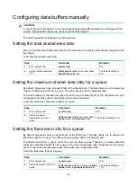
Configuring data buffers manually
CAUTION:
To avoid impact to the system, do not manually change data buffer settings to avoid impact to the
system. If large buffer spaces are needed, use the Burst feature.
The switch supports configuring only cell resources.
Setting the total shared-area ratio
After you set the total shared-area ratio for cell resources, the rest is automatically assigned to the
fixed area.
To set the total shared-area ratio:
Step Command Remarks
1.
Enter system view.
system-view
N/A
2.
Set the total shared-area
ratio.
buffer egress
[
slot slot-number
]
cell
total-shared
ratio ratio
The default setting is
91%.
Setting the maximum shared-area ratio for a queue
By default, all queues have an equal share of the shared area. This task allows you to change the
maximum shared-area ratio for a queue. The other queues use the default setting.
The actual maximum shared-area space for each queue is determined by the chip based on your
configuration and the number of packets to be received and sent.
To set the maximum shared-area ratio for a queue:
Step Command
Remarks
1.
Enter system view.
system-view
N/A
2.
Set the maximum
shared-area ratio for a
queue.
buffer egress
[
slot slot-number
]
cell
queue queue-id
shared ratio ratio
The default setting is 33%.
Setting the fixed-area ratio for a queue
By default, all queues have an equal share of the fixed area. This task allows you to change the
fixed-area ratio for a queue. The other queues equally share the remaining part.
The fixed-area ratio for a queue cannot be used by other queues. Therefore, it is also called the
minimum guaranteed buffer for the queue. The sum of fixed-area ratio configured for all queues
cannot exceed the total fixed-area ratio. Otherwise, the configuration fails.
To set the fixed-area ratio for a queue:
Step Command Remarks
1.
Enter system view.
system-view
N/A
2.
Set the fixed-area ratio for a
queue.
buffer egress
[
slot slot-number
]
packet
queue queue-id guaranteed ratio ratio
The default setting is
13%.
Summary of Contents for FlexFabric 5940 Series
Page 23: ...17 Figure 3 QoS processing flow ...
Page 84: ...78 Figure 26 MPLS label structure ...
Page 91: ...85 Switch burst mode enable ...


