background image


30 

FM 3180 Installation Guide


8


Installing Transceivers and Cables 

For cables without a built-in transceiver, before you can connect the cables, you need to install the 
appropriate transceivers into the QSFP28 ports that need to be cabled.  

Before you can connect cables, you need to install transceivers into the QSFP28 ports that need to be 
cabled. 

Once you mount the fabric module, you can attach the cables. 

IMPORTANT: 

Refer to the 

HPE Composable Fabric Support Matrix

 for supported cables and 

transceivers. 

Installing Transceivers 

For cables without a built-in transceiver, before you can connect the cables, you need to install the 
appropriate transceivers into ports to be cabled.  

You should have the transceivers you ordered for your HPE fabric module.  

The FM 3180 supports Quad Small Form-Factor Pluggable (QSFP28) transceivers in QSFP ports 49-56. 

Important

: Fiber optic modules are dust-sensitive. Always keep the plug in the optical bore when a fiber 

optic cable is not installed or when you store the module. When you do remove the plug, retain it for 
future use. 

QSFP28 

Each QSFP28 set of ports can be configured to run at either 100 GbE or a 40 GbE. Depending on the 
desired port speed and connection type, select the appropriate transceiver as listed in the following 
document: 


HPE Composable Fabric Support Matrix 

Inserting Transceivers 

Verify that you have the correct transceiver for the cable and connection being planned for the port. Note 
that some cables have a built-in transceiver. 

Carefully push the transceiver into the QSFP28 receptacle until it is seated and locks in place.  If it stops 
before installed, remove, reorient and re-install the transceiver. 

Note that all transceivers are keyed, insuring that they are installed with the correct orientation. 

Connecting QSFP28 Cables 

To connect a cable to the fabric module, verify that the correct transceiver is installed and then plug the 
cable into the transceiver until it locks in place. Note that all transceivers and cables are keyed, insuring 
that they are installed with the correct orientation. 

QSFP28 Breakout Cables 

In addition, you can order QSFP28 cables that break out four separate 10Gbps or 25 Gbps channels. 

Summary of Contents for FM 2072

Page 1: ...HPE Composable Fabric 5 0 FM 3180 Fabric Module Installation Guide Part Number P14110 001a Published February 2019 Edition 2 ...

Page 2: ...up Intel Itanium Pentium Intel Inside and the Intel Inside logo are trademarks or registered trademarks of Intel Corporation or its subsidiaries in the United States and other countries Safety The HPE fabric module system is classified as a class 1 telecommunications laser product employing embedded class 1 lasers and complies with the following THIS PRODUCT COMPLIES WITH FDA RULE 21 CFR SUBCHAPTE...

Page 3: ...cuit Overloading 9 Reliable Earthing Grounding 9 Mechanical Loading 9 Equipment Protection 9 Equipment Specifications 9 UPS 10 Cabling 10 Unpack the Fabric Modules 10 Verify Equipment Delivered 10 Part Numbers 11 Cables and Transceivers 11 Record the MAC Address 11 Installation Considerations 11 Power 11 Working with Optical Cables 11 3 Installing HPE FM 3180 12 Rack Mounting HPE FM 3180 12 Establ...

Page 4: ...odule Fabric 21 Five Module Fabric 22 Six Module Fabric 23 Seven Module Fabric 24 7 Adding a Fabric Module to an Existing Fabric 25 Adding Module 7 to a Six Module Fabric 25 Adding Module 6 to a Five Module Fabric 26 Adding Module 5 to a Four Module Fabric 27 Adding Module 4 to a Three Module Fabric 28 Adding Module 3 to a Two Module Fabric 29 8 Installing Transceivers and Cables 30 Installing Tra...

Page 5: ...hardware support information including cable and transceiver support information HPE Composable Fabric Manager 5 0 Installation Guide HPE Composable Fabric Module 5 0 Administrator Guide using Linux and CLI HPE Composable Fabric 5 0 FM 3032Q Fabric Module Installation Guide HPE Composable Fabric 5 0 FM 2072 Fabric Module Installation Guide HPE Composable Fabric Manager Online Help which is availab...

Page 6: ...s i No user serviceable parts are inside the chassis other than the power supplies and fan assemblies Contact HPE for all repairs i Only qualified personnel should service or replace HPE fabric modules The HPE fabric module contains multiple separate power sources Always make certain that all power sources are disconnected before servicing the unit Electrostatic Discharge Precautions Use Electrost...

Page 7: ...gned to provide reasonable protection against harmful interference when the equipment is operated in a commercial environment This equipment generates uses and can radiate radio frequency energy and if not installed and used in accordance with the instruction manual may cause harmful interference to radio communications Operation of this equipment in a residential area is likely to cause harmful i...

Page 8: ...eeded Installation q Install the fabric module s in rack s q Install power cables The fabric module automatically powers up and boots Verify green LEDs on power supplies q Establish a management connection to the fabric module through either the CONSOLE port or the MGMT port q Install all cables as per the cabling plan and build the fabric using either q FM 1006 interconnect or q Direct connect q ...

Page 9: ...includes two power cables each 1 5 meters in length which comply with appropriate country standards When you connect the equipment to the supply circuit do not overload the circuits You need to consider the overcurrent protection and supply wiring Review the equipment nameplate ratings before you start making connections Make certain that all input connections are accessible at all times and disco...

Page 10: ...in the shipment check for any shipping damage and verify that the components received match those ordered Equipment Description Four hot swappable fans Installed in chassis A red tab warm side indicates airflow from front to rear I O to power panel A blue tab cool side indicates airflow from rear to front power to I O panel Two power supplies Installed in chassis A red cable latch warm side indica...

Page 11: ...the MAC address for fabric module setup Installation Considerations Keep the following considerations in mind when installing and cabling fabric modules Power Verify that power cords easily reach from the power outlets to the fabric module power supply modules Ensure that appropriate grounding and current surge protection are in place before connecting the fabric module to a power source All input...

Page 12: ...h the rack slot holes press the rail latch and release to secure the rail Pull to expand the rail and repeat to latch the other end to the rack IMPORTANT Since you need to install the fabric module from the back of the rack you need to position the rails in rack slots i e top of rack that allow the fabric module and rails to clear any obstructions such as power strips For example if you are instal...

Page 13: ... 8 The fabric module is shipped with power supplies installed as ordered Route and connect the power cables into separate circuits in the rack Important For redundancy connect the two power supplies to separate power sources Establishing a Management Connection You can establish a management connection to the fabric module using either method Connect the console device to the Console port and esta...

Page 14: ... DHCP If you are installing the fabric module in an environment that uses DHCP and the DHCP server has been configured as needed the fabric module is ready to communicate with HPE Composable Fabric Manager After the link is established use the HPE Composable Fabric Manager UI to configure the fabric module see the HPE Composable Fabric Manager 5 0 Online Help If you are using static IP addresses o...

Page 15: ...ed This is especially true when a fabric contains fabric modules of different speed capacities for example FM 2072 which operates at 10 Gbps per port and FM 3180 which operates at 25 Gbps per port In release 5 0 the installed transceiver determines the port speed In a mixed environment 40 Gb s QSFP transceivers must be installed in QSFP fabric ports capable of operating at 100 Gb s Connect each FM...

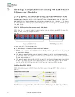
Page 16: ...e Fabric The FM 1006 contains the following ports 12 MPO24 ports to connect to as many as six fabric modules MPO24 ports to connect other FM 1006 modules thereby extending the fabric connecting many 7 or more fabric modules The upper Composable Fabric ports are labeled E1 through E6 and the lower Composable Fabric ports are labeled W1 through W6 You will connect E1 and W1 to one fabric module E 2 ...

Page 17: ...rt 53 FM 1006 upper red port for example W1 Cable connector 3 fabric module port 55 And Cable connector 1 fabric module port 52 Cable connector 2 fabric module port 54 FM 1006 lower blue port for example E1 Cable connector 3 fabric module port 56 The FM 3180 Fabric ports are shown here FM 1006 Composable Fabric Example The following illustration shows a network topology that connects the Composabl...

Page 18: ...nected to expand the Composable Fabric Three 24 fiber MTP cables are used to connect to an FM 1006 device to the next FM 1006 device and an additional three cables are used to connect to the previous FM 1006 device To connect FM 1006 devices together use 24 fiber MTP to MTP cables available in varying lengths 1 3 5 10 20 and 100M You need six cables to expand an FM 1006 device to other FM 1006 dev...

Page 19: ...mple if you are connecting five FM 3180 modules number them 1 2 3 4 5 You can affix a label to each fabric module for identification Refer to the appropriate section that follows for your fabric size It may be easiest to start with fabric module 1 connect the three top ports 51 53 and 55 as defined in the appropriate section that follows for your fabric size Then continue with cabling from module ...

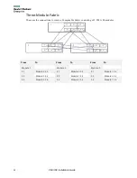
Page 20: ...he connections to create a Composable Fabric consisting of 3 FM 3180 modules From To From To From To Module 1 Module 2 Module 3 51 Module 2 52 51 Module 3 52 51 Module 1 52 53 Module 3 54 53 Module 1 54 53 Module 2 54 55 Module 2 56 55 Module 3 56 55 Module 1 56 ...

Page 21: ...omposable Fabric consisting of 4 FM 3180 modules From To From To From To Module 1 Module 2 Module 3 51 Module 2 52 51 Module 3 548 51 Module 4 52 53 Module 3 54 53 Module 4 54 53 Module 1 54 55 Module 4 56 55 Module 1 56 55 Module 2 56 Module 4 51 Module 1 52 53 Module 2 54 55 Module 3 56 ...

Page 22: ...g of 5 FM 3180 modules From To From To From To Module 1 Module 2 Module 3 51 Module 2 52 51 Module 3 52 51 Module 4 52 53 Module 3 54 53 Module 4 54 53 Module 5 54 55 Module 4 56 55 Module 5 56 55 Module 1 56 Module 4 Module 5 51 Module 5 52 51 Module 1 52 53 Module 1 54 53 Module 2 54 55 Module 2 56 55 Module 3 56 ...

Page 23: ...To From To From To Module 1 Module 2 Module 3 51 Module 2 52 51 Module 3 52 51 Module 4 52 53 Module 3 54 53 Module 4 54 53 Module 5 54 55 Module 4 56 55 Module 5 56 55 Module 6 56 Module 4 Module 5 Module 6 51 Module 5 52 51 Module 6 52 51 Module 1 52 53 Module 6 54 53 Module 1 54 53 Module 2 54 55 Module 1 56 55 Module 2 56 55 Module 3 56 ...

Page 24: ...ic modules 1 2 and 3 From To From To From To Module 1 Module 2 Module 3 51 Module 2 52 51 Module 3 52 51 Module 4 52 53 Module 3 54 53 Module 4 54 53 Module 5 54 55 Module 4 56 55 Module 5 56 55 Module 6 56 Module 4 Module 5 Module 6 51 Module 5 52 51 Module 6 52 51 Module 7 52 53 Module 6 54 53 Module 7 54 53 Module 1 54 55 Module 7 56 55 Module 1 56 55 Module 2 56 Module 7 51 Module 1 52 53 Modu...

Page 25: ... To cable a 7th fabric module added to a 6 module fabric follow these steps in sequence to move and add cables Cable Connection Steps to accomplish Module 6 51 to Module 7 52 1 Unplug Module 1 52 2 Plug freed end into Module 7 52 Module 5 53 to Module 7 54 3 Unplug Module 1 54 4 Plug freed end into Module 7 54 Module 4 55 to Module 7 56 5 Unplug Module 1 56 6 Plug freed end into Module 7 56 Module...

Page 26: ...mplish Module 3 55 to Module 6 56 1 Unplug Module 1 56 2 Plug the freed end into Module 6 56 Module 4 53 to Module 6 54 3 Unplug Module 1 54 4 Plug freed end into Module 6 54 Module 4 55 to Module 1 56 5 Unplug Module 2 56 6 Plug freed end into Module 1 56 Module 5 51 to Module 6 52 7 Unplug Module 1 52 8 Plug freed end into Module 6 52 Module 5 53 to Module 1 54 9 Unplug Module 2 54 10 Plug freed...

Page 27: ... 56 1 Unplug Module 1 56 2 Plug the freed end into Module 5 56 Module 3 53 to Module 5 54 3 Unplug Module 1 54 4 Plug freed end into Module 5 54 Module 4 51 to Module 5 52 5 Unplug Module 1 52 6 Plug freed end into Module 5 52 Module 4 55 to Module 2 56 7 Unplug Module 3 56 8 Plug freed end into Module 2 56 Module 4 53 to Module 1 54 9 Unplug Module 2 54 10 Plug freed end into Module 1 54 Module 3...

Page 28: ...6 1 Unplug Module 2 56 2 Plug the freed end into Module 4 56 Module 2 53 to Module 4 54 3 Unplug Module 1 54 4 Plug freed end into Module 4 54 Module 3 55 to Module 2 56 5 Unplug Module 1 56 6 Plug freed end into Module 2 56 Module 3 51 to Module 4 52 7 Unplug Module 1 52 8 Plug freed end into Module 4 52 Module 3 53 to Module 1 54 9 Unplug Module 2 54 10 Plug freed end into Module 1 54 Module 3 5...

Page 29: ...e fabric follow these steps in sequence to move and add cables Cable Connection Steps to accomplish Module 2 55 to Module 3 56 1 Unplug Module 1 56 2 Plug the freed end into Module 3 56 Module 1 53 to Module 3 54 3 Unplug Module 2 54 4 Plug freed end into Module 3 54 Module 2 51 to Module 3 52 5 Unplug Module 1 52 6 Plug freed end into Module 3 52 Module 3 51 to Module 1 52 7 Plug Module 3 51 to M...

Page 30: ... you store the module When you do remove the plug retain it for future use QSFP28 Each QSFP28 set of ports can be configured to run at either 100 GbE or a 40 GbE Depending on the desired port speed and connection type select the appropriate transceiver as listed in the following document HPE Composable Fabric Support Matrix Inserting Transceivers Verify that you have the correct transceiver for th...

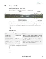
Page 31: ...s Each QSFP28 port has 4 LEDs which indicate the mode as follows LEDs Mode Additional Left LED lit green Flashing traffic 100G 40G mode Flashing LED Indicates that traffic is passing In 100G 40G mode traffic is split into blocks across the four lanes There are no individual ports Traffic passes across the four lanes 1st and 3rd LED lit green Flashing traffic 2 x 50 mode Lanes 1 2 have traffic spre...

Page 32: ...or serial access to the fabric module for management The CONSOLE port has no LED USB The USB port located between the MGMT port and CONSOLE port has no LED P 1 P 2 and STAT LEDs The P 1 P 2 and STAT LEDs are described in the table below RST The I O panel has a recessed RESET button for manual fabric module reset LED State State P 1 Green Power supply 1 power supply labeled PWR1 is plugged in and s...

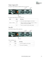
Page 33: ... Meaning PWR1 or PWR2 green The power supply is plugged in and running red There is no power to that power supply but there is power to the other power supply off There is no power to either power supply Fan LED Each of the fans has an LED as shown here The fan LED states are LED State Meaning Fan green The fan is plugged in and running off The fan is not operating ...

Page 34: ...rt the replacement power supply module into the chassis slot until fully seated and the latch snaps into place NOTE Each powersupplymoduleis keyed to insure correct orientation 4 Connect the power cord 5 Verify that the Power LED lights solid green Replacing a Fan Module A single failed fan module can be hot swapped as follows 1 Press the latches inward against the pull tabs and pullthe fanmodule ...

Page 35: ...perating Altitude 60 to 2000 meters 196 to 6562 feet Operating Temperature 0 C 45 C 56 F 113 F Humidity 5 90 non condensing Acoustics 100dBA at 100 fan speed Interfaces Front 48 SFP28 25 GbE ports 8 QSFP28 ports Rear CPU BMC shared Management RJ45 and Console RJ45 ports USB Type A Cooling 3 1 redundant fans front to back and back to front system cooling Approvals EMC CN GB9254 2008 EU EN55022 EN55...

Reviews: