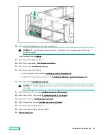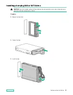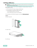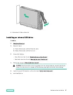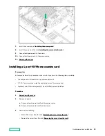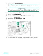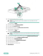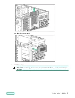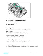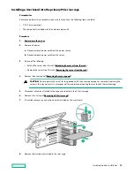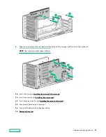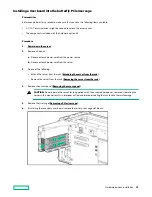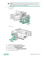
13. Connect each power cord to the power source.
Expansion slot options
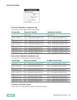
Processor-to-PCIe slot assignment
The PCIe slots are mapped to specific processors, as described in the following table.
Proc
Primary riser
Secondary riser
Tertiary riser
Primary 8x2 NVMe riser
7 slot PCIe
6 slot
+ NVMe
7 slot PCIe
6 slot
+ NVMe
2 slot PCIe
NVMe slim NVMe Mezz
1
Slots 5, 6, 7
Slots 5, 6, 7
+ 2 NVMe
(J4)*
—
—
—
8 NVMe
—
2
—
—
Slots 12, 13,
14
Slots 12, 13, 14
+ 2 NVMe (J3)*
Slots 15, 16
—
—
3
Slots 1, 2, 3, 4 Slots 2, 3, 4
+ 2 NVMe
(J3)*
—
—
—
—
8 NVMe
4
—
—
Slots 8, 9, 10,
11
Slots 9, 10, 11
+ 2 NVMe (J4)*
—
—
—
* To locate the J3 and J4 ports, see
For example, PCIe slot 8 is operational when:
• The 7 slot PCIe riser board is installed in the butterfly riser cage.
• Processor 4 is installed.
Supported PCIe form factors
All slots support full-height expansion cards. Use the following information to find supported lengths for each slot. The
tables in this section describe the slot description and the supported form factor for each slot in each riser cage. For
information about the slot numbering, see
Hardware options installation
98

