background image

User manual - Machine Automation Solution - V3R003            


64 / 102

same field. 


Important

All guides created for the same field from the current work session are visible, so it is possible
to use a guide saved in another work session but for the same physical location.

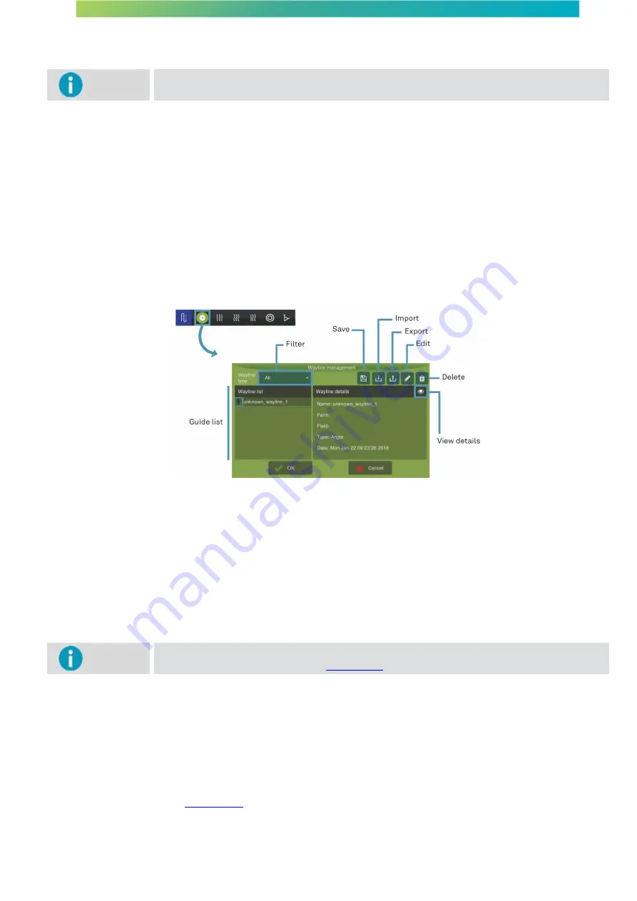
When selecting a guide from the list, the system presents the following information on it:

·

Guide name;

·

Name of the farm where the guide was created;

·

Name of the field where the guide was created;

·

Guide type;

·

Data of creation of the guide.

By clicking on  the 

View details  option

, you are able to preview the guide  according  to  its  type  (curve,  angle,  or  pivot,  for

example).  On  the  list  it  is  possible  to  recognize  the 

Active  guide 

on  the  field  through  the  icon  marked  with  a  lightning

image.

Figure - Guide management

The visualized guides may be filtered by 

Guide type

:

·

Curve;

·

Linear;

·

Pivot;

·

Angle;

·

Adaptive;

·

Line map.


Important

Line maps are not created through the operation screen. They are only available on the list
through guide importing. See topic 

Import guide

.

Line map

Guides of type 

Shape file 

actually correspond to a set of lines known as a 

Line map

. On the on-board computer, the

map can only appear through importing and can be externally created in three ways:

·

It can be created in an office using a specific software;

·

It can be created by exporting a guide from the on-board computer that the user exported in a 

Line map

format. See topic 

Export guide

;

·

It may be a guide created in an on-board device from a manufacturer other than Hexagon Agriculture. In this

case, if there is incompatibility, the guide is imported as a 

Line map

.

Summary of Contents for AgrOn Ti10

Page 1: ...Copyright 2019 by Hexagon agriculture All rights reserved...

Page 2: ...1 1 Alerts 17 7 2 Connectivity information 22 7 3 Lightbar 23 7 4 Information configuration 23 7 5 Main menu 24 7 5 1 Guide 24 7 5 2 Visualization 24 7 5 3 Tools 25 7 5 4 Configuration menu 29 7 6 Con...

Page 3: ...80 13 2 Advanced mode 81 13 2 1 Change passw ord 81 13 2 2 Logging 82 13 2 3 Netw ork 83 13 2 4 Activation 84 13 2 5 Firmw are update 85 13 2 6 External settings 86 13 2 7 Data synchronization 87 13 2...

Page 4: ...ctions contained in the User Manual and the Safety Manual issued by the manufacturer of the farming machinery The images in this manual are purely illustrative Screens and visual elements may differ f...

Page 5: ...r the operation and safety of the agriculture machinery Warning Verify the integrity of the results of the display s measurements after a fall or misuse transport modification or when stored for long...

Page 6: ...ts Although this product fully meets the strictest regulations and standards in force Hexagon Agriculture cannot completely exclude the possibility of interference in the instrument caused by intense...

Page 7: ...ble 5 Power cable 6 Arm mounting bracket 7 Clamp mounting bracket 8 Flashdrive 9 Documentation Figure System components 3 1 2 Views Warning The display was designed to be used with the touch of your f...

Page 8: ...ion 3 1 3 Product identification The product type model and serial number are indicated on a label on the back of the display Record the type and serial number in your manual and inform them when cont...

Page 9: ...User manual Machine Automation Solution V3R003 9 102...

Page 10: ...stallation proceed as follows 1 Mount the clamp to the desired location in the vehicle To mount the clamp wrap the bow around the tube insert the base and fasten with hex nuts Use a socket wrench for...

Page 11: ...rder to ensure that the signal is received in all directions A clear view of the sky to the horizon in all directions is recommended for the ideal reception of satellites as obstacles close to the ant...

Page 12: ...User manual Machine Automation Solution V3R003 12 102 Figure Ti10 monitor display antenna installation...

Page 13: ...he conventional launch mode go to next topic Job section Important The fast start mode is only available for the display with solely and exclusively the Guidance activated To enable or disable this fu...

Page 14: ...or the displays with solely and exclusively the Guidance activated To enable or disable this function select the Fast mode ON OFF option located on the right side of the job section list The display w...

Page 15: ...e presented on the list and click OK to select 12 The list of activities is presented 13 Select an activity from the list or select New to insert a new activity 14 Enter the activity name and select O...

Page 16: ...job section on fast start mode proceed as follows 1 Select a Job section among those presented on the screen 2 Select option Delete 3 A confirmation message will be displayed 4 Confirm the operation b...

Page 17: ...lerts 2 Notifications bar 3 Connectivity information 4 Operation bar 5 Lightbar 6 Suspended operation 7 Operation information Figure Operation screen with lightbar 7 1 Upper bar 7 1 1 Alerts Important...

Page 18: ...alert table is presented below Name Summary Description Monitoring alert Rule violated A monitoring rule has been violated Contact your supervision High temperature High system temparature Operation...

Page 19: ...ached The system is unable to reach seed recommendation If you have not received an alert that the operation is outside the speed range the calibration or the minimum and maximum motor speed parameter...

Page 20: ...enna may cause GNSS malfunction GNSS Low precision No RTK The system is not using RTK positioning which leads to low GNSS accuracy Ensure that the RTK base is on the radio is connected the baud is cor...

Page 21: ...n Odometer Close to the limit The system is approaching the established distance limit You must be careful not to damage the implement when the limit is reached Odometer Limit reached The system has e...

Page 22: ...nd that the hydraulic is correctly engaged Sensor Unresponsive sensor The system is not reading the sensor Please ensure that the cables and connectors are properly installed and or the sensor is not...

Page 23: ...isplayed at the top of the operation screen and displays the deviation of the vehicle from the guide being executed The squares represent the LEDs that light up when the configured offset is reached V...

Page 24: ...th the main menu buttons Figure Options to the left of the screen 7 5 1 Guide Guidance types are used to define a guideline on the field The display operates with the following Icon Description Waylin...

Page 25: ...decreases the zoom on the operation screen You can zoom in and out of the maps using the pinch gestures making it quicker and easier for the user to zoom in and out Figura Pinch gesture Delete trail...

Page 26: ...ceed as follows 1 Press on the Marker option and then press the Manage markers icon 2 In the layer manager press option Create new marker layer 3 Insert a new name for the layer and confirm Example an...

Page 27: ...for marking the perimeter and press OK to confirm 4 The system will begin marking the perimeter 5 When you finish marking press the stop option 6 The system will display a message to confirm creating...

Page 28: ...rker or perform the adjustment the vehicle cannot me in operation or in motion New position To mark a new position proceed as follows 1 Position the tractor where you want to add the marker 2 On the O...

Page 29: ...arameter settings are made available Important To view all the available settings alter the system mode to Advanced Important When you start the system for the first time only the Vehicle Implement an...

Page 30: ...aying the controls and information for using these applications To access the bar for a feature proceed as follows 1 On the Operation screen with one touch drag the bottom of the screen upwards 2 The...

Page 31: ...model used on your device The available options are External GGA NMEA external GNSS Messages provided and recommended frequencies GGA minimum 5Hz and desirable up to 20Hz VTG minimum 5Hz and desirabl...

Page 32: ...using TerraStar L TerraStar C TerraStar C Pro RTK or NTRIP correction signals an alarm will indicate that the accuracy is low if the correction service is not active or the position estimate has not y...

Page 33: ...that may be used to availability NMEA messages for the Novatel GNSS for external devices see topic NMEA output NTRIP output Important This setting will only be available for the NTRIP GNSS model whic...

Page 34: ...decreases beyond a defined limit The RTK ASSIST service is available by subscription Speed filter Important This setting will only be available for the GNSS model Max7 Max7 8 and Max8BeiDou This opti...

Page 35: ...alert will be displayed on the operation screen To access NTRIP support proceed as follows 1 Press the GNSS option in the Settings menu 2 In the GNSS model select NTRIP OEM7 NTRIP ou OEM617 NTRIP 3 Se...

Page 36: ...sending the corrections Timestamp correction Time of the last correction received from the base GGA timestamp Time of the last vehicle position reference sent to the base 8 1 2 NTRIP Server NTRIP serv...

Page 37: ...ector B and a suitable cable is required To activate this output proceed as follows 1 In Settings menu select option GNSS Important The system mode should be advanced so that the GNSS option becomes a...

Page 38: ...messages may be needed for complete information Important The compatibility module is available for the OEM and Novatel models The Compatibility mode is used to transmit the desired GAA correction qua...

Page 39: ...ls information regarding location accuracy will be presented which allows for more accurate identification of vehicle positioning According to technical information about Novatel models on displays ho...

Page 40: ...rning Incorrect vehicle selection may compromise the entire validity of the work Figure Vehicle selection Important If no vehicles have been created it will not be possible to access the Configuration...

Page 41: ...elled the distance from the axis to the pin equals the distance from the axis to the section closes to the spray bar In this case the pin axis in the implement s configuration should be zeroed As for...

Page 42: ...select the Save option 9 3 Removing the vehicle Important Feature available only in Advanced mode To remove a vehicle proceed as follows 1 Select the Vehicle option in the Configuration menu 2 Select...

Page 43: ...n in the Configuration menu 2 Select the desired implement in the box to the left of the screen 3 Ensure the settings are correct and press OK Figure Implement selection 10 1 Inserting a new implement...

Page 44: ...g the implement Important Feature available only in Advanced mode To edit an implement proceed as follows 1 Select the Implement option in the Configuration menu 2 Select the implement you wish to edi...

Page 45: ...actor in order to have a minimum 48l min flow in the hydraulic system To view details about the tests check the specific topics Implement tests for the planting control activity topic Planting tests I...

Page 46: ...olute 11 1 Settings The following settings are available Width in meters Sensitivity in meters Side overlap in meters Activity overlap Yes or No Overlap rate Wayline settings Reverse detector Odometer...

Page 47: ...igure Lateral overlap Activity overlap Yes or No Reapplies to an already treated area overlapping the activity on the application map For example if an implement passes over an area where it has alrea...

Page 48: ...topic Figurae Guide settings 11 1 2 1 Saving mode The type of guide saving must be previously defined To define the way the guides are saved proceed as follows 1 Select the Guidance option in the Conf...

Page 49: ...option as the positions of the guides are changed it is not possible to return the position of the original guide If you intend to work again in the area already applied using the same guides it is a...

Page 50: ...peration screen the equipment has manual controls so that the operator can adjust the position of the GNSS the adjustment is made every 2 centimeters to the side indicated by the user Important The po...

Page 51: ...For example the display will consider that the operator finalized capturing the adaptive curve and will generate new lines based on the new reference as soon as the vehicle direction varies more than...

Page 52: ...l trajectory by inserting intermediary points on the curve to be shown to the operator The value does not affect the pilot s behavior however increasing it causes a larger processor load and slowness...

Page 53: ...tion Warning For using the automatic pilot the reverse detector must be activated Important In case you want to inform the display that the reverse direction is inverted simply select the Invert direc...

Page 54: ...nd its features in operation check topic Monitoring the operation The odometer s function is to measure the distance traveled The number that shows indicates the distance already traveled by the vehic...

Page 55: ...een On and Off Figure Apply off the map 11 2 Operation The operation is started by selecting the suspended operation option in the center of the operations screen Important The application will only b...

Page 56: ...int B to mark the end of the trajectory Warning The smallest distance between points of line A B is of 30 meters The longest distance between points A B will be 20km Important You can cancel a guide c...

Page 57: ...ark the end of the trajectory Warning The smallest distance between points A and B is of 30 meters The longest distance between points A B will be 20km Warning In case reference curve A B intersects w...

Page 58: ...end of the trajectory Warning The smallest distance between points A and B is of 30 meters The longest distance between points A B will be 20km Figure Adaptive curve Figure Adaptive curve consideratio...

Page 59: ...ing guide Configuring trajectory points Icon Description Guide Line A Angle Point A To draw the guide line proceed as follows 1 On the operation screen select the Guide option on the left side menu 2...

Page 60: ...with an active guide Important The Realign Manual adjustment and Disable guide options will only be visible when a guide is loaded into the field Icon Description Realign the position of the GNSS ant...

Page 61: ...tion of the original guide If you intend to work again in the area already applied using the same guides it is advisable to use the other behavior that would be to realign by creating a new guide Real...

Page 62: ...ng the displacement will be presented on the top of the screen 3 Pulse the arrows for the desired direction Important Each time the arrow is pressed the line is moved 2cm to the chosen side Figura Man...

Page 63: ...ows 1 With the guide active press the Unload guide option 2 An option asking if you wish to deactivate the guide will be shown 3 Select Yes to confirm the operation Figure Disable guide 11 2 3 Managin...

Page 64: ...through the icon marked with a lightning image Figure Guide management The visualized guides may be filtered by Guide type Curve Linear Pivot Angle Adaptive Line map Important Line maps are not create...

Page 65: ...y guide will be lost and replaced by the new one The system allows one temporary guide of each guide type To ensure you can access it again save your temporary guide Warning When you try to save a gui...

Page 66: ...parallel lines Your map must contain at least 75 points to be imported The imported guides will show on the list of guides Important In case the imported guide has the same name of a previously saved...

Page 67: ...es to the left and to the right Exporting creates a Line map for which it is no longer possible to identify the original guide Icon Description Guide Guide management Export To export guides through t...

Page 68: ...he Guide manager proceed as follows 1 On the operation screen select the Guide option followed by Guide management 2 Select the guide you wish to edit from the list of guides 3 Select the Edit option...

Page 69: ...ide Guide management Delete To edit a guide name through the Guide manager proceed as follows 1 On the operation screen select the Guide option followed by Guide management 2 Select the guide you wish...

Page 70: ...pe format with the purpose of using the same planned and standardized application trajectory Markers Marcadores criados para indica o de pedras buracos formigueiros reas molhadas entre outros Settings...

Page 71: ...e transfer is finished press OK 12 1 2 Exporting a prescription map To export a recommendation map or line map proceed as follows 1 Select option Files from the Configuration menu 2 Select option Expo...

Page 72: ...ight and to the left and press OK 7 Wait for the file transfer Warning It is possible to select more than one file to export Figure Data transfer Items Warning To learn more about the Original guide o...

Page 73: ...e enabled when the Send files to cloud automatically option is automatically selected To export pending files proceed as follows 1 Select Files from the Configuration menu 2 Select option Export to US...

Page 74: ...Warning To learn more about importing guides see topic Import guide Important To import a perimeter select the Prescription map option 12 3 Deleting data To delete data stored in the display proceed...

Page 75: ...rocessor CPU and screen LCD temperatures the serial number as well as shows information on the GNSS data among others Figure About 13 1 1 1 Version Information about the system is composed of the foll...

Page 76: ...the progress bar is complete Uninstalling software update In Uninstall software update it is possible to uninstall the latest installed version Installing config update In Install config update it is...

Page 77: ...to import It is possible to select more than one backup 4 Select option Import in the upper right corner 5 Wait for the process to finish and press OK Collecting diagnostic information When an error...

Page 78: ...resented Ethernet interface MAC address IP address Figure Network state 13 1 1 5 Remote access Here it is possible to turn remote access on or off When off the display will not be viewed nor operated...

Page 79: ...ouch will alter time in 15 minuts from the UTC Coordinated Universal Time Theme Select the default or night theme for the operation screen and confirm 13 1 3 System mode This option allows alternating...

Page 80: ...advanced tests This operation can only be performed entering a password To access the assistance options proceed as follows 1 Select option Settings from the Configuration menu 2 Select option Suppor...

Page 81: ...Machine monitor Cutting section Logic controller Ant killer controller Reset Clears the address for all the devices connected to the CAN Device info Shows the software version and the external power...

Page 82: ...ct option Logging The file may be stored in the following ways Single file This way the log is saved in a single application file separated by work session and by implement type Daily This way the app...

Page 83: ...For Wi Fi settings see the settings Wi Fi topic 13 2 3 1 Mobile data settings By pressing the Mobile data button the connection screen is displayed Figure Mobile data To configure the connection proc...

Page 84: ...the Wi Fi button the connection screen is displayed Figure Wi Fi network To configure the network proceed as follows 1 Select the Wi Fi network 2 Press OK Important In case your Wi Fi network is not...

Page 85: ...Press Import 3 Press Activate 4 Check the success or the failure message Figure Activation 13 2 5 Firmware update Important Feature available only in the Advanced mode This feature allows the user to...

Page 86: ...ion if your button is the kind that returns to the normal state after being pressed and select option Maintained if your switch is the kind that maintains its state after being pressed Important When...

Page 87: ...5 Select option On so that the update is ready for installation through the system manager In the Off state it is not possible to update the software because there is no communication with the server...

Page 88: ...e update time is configurable The range depends on the type of antenna used power of the signal and the presence or absence of obstacles on the way but it is usually in the range between 2 meters Figu...

Page 89: ...the Configuration menu 2 Enter Advanced mode 3 Select the RFIDs tag list option 4 Click on the tag you want to change 5 The tag information screen is displayed 6 Select the option to reset the trailer...

Page 90: ...to the topic firmware update Warning If the Truck device is not available or working correctly a message will be displayed when selecting this option Trailer If you selected the Trailer option the lis...

Page 91: ...oi estabelecida e que o firmware est atualizado caso deseje ter acesso as configura es 1 Selecione o dispositivo que deseja configurar para isso clique sobre o n mero de s rie 2 Selecione a op o Confi...

Page 92: ...long to the same set in the case of upgrading to the Trailer 13 2 9 2 Device config Important This procedure is only available for the trailer vehicle To configure a device proceed as follows 1 In the...

Page 93: ...railer in meters Trailer position Number corresponding to the order of the trailer in the connection sequence the trailer in position 1 corresponds to the one closest to the truck cabin Accelerometer...

Page 94: ...assistance Technical support access is done via Hexagon Agriculture s web support software 14 1 Visualization mode To have remote access in Visualization mode the technician needs to have the device...

Page 95: ...R003 95 102 Figure Operation mode icon Important Remote access may be interrupted at any time by pressing the access icon on the bottom right corner of the screen The display will display a message fo...

Page 96: ...x Back USB 1 x Back RS 232 2 x Back Models according to the GNSS module Model Ti10 GNSS module Novatel OEM7500 Settings Channels 181 L1 L2 L5 B1 B2 E5b AltBOC Constellations GPS GLONASS BeiDou Galileo...

Page 97: ...gy Bands LTE Band 1 2100 MHz Band 3 1800 MHz Band 5 850Mhz Band 7 2600 MHz Band 8 900 MHz Band 28 700MHz HSPA UTMS Band 1 2100 MHz Band 5 850 MHz Band 8 900 MHz EDGE GSM GPRS EGSM 900 900 MHz DCS 1800...

Page 98: ...is operated in a commercial environment This device generates uses and may radiate radiofrequency energy if it is not installed in accordance with the instruction manual supplied by the manufacturer...

Page 99: ...put into operation without restriction in a Member State of the European Union Warning Relative compliance to countries whose regulations are not covered by European Directive 1999 5 EC must be approv...

Page 100: ...ems Perform calibration and simulation Check the filter Check the valve and flow meter cabling Check if the vehicle is below the operation speed range Application failure when entering and exiting bor...

Page 101: ...ne and the reference surface Latitude is measured in degrees North and South of the equatorial plane between 90o South at the South Pole 90o North at the North Pole Longitude Longitude is measure alon...

Page 102: ...be void when a The product s serial number or identification label are removed altered b The product seal is removed c The product is connected to a voltage other than that specified in the installati...

Reviews: