Appendix
H000002007-RDS User Manual
│
Version 5.0.0 (2018-09-17)
│199
M.1.14 ABERLINK
Trigger button
3State button - Left
3State button - Right
Short
Hit Pt
Cancel
Validate
Long
Burst Pts
Aberlink3D
Aberlink3D is designed to work with many different kinds of measuring devices including manual CMM's,
CNC's, arms and vision systems. Installation is the same whatever device you are using. The Green
Keylock Dongle will define which options can be accessed by Aberlink3D via machine set up -> scales.
Please see “Aberlink3D Keylock Installation”.
Run the setup.exe from the CD. Click next until you come to the select components - custom installation.
Choose “Retrofit”. In practice it makes no functional difference which option you choose. This option only
sets the reference picture and relevant section of the language file, neither of which is used by the Absolute
Arm. Click through the next windows. Various other packages will be installed i.e. .Net framework etc.
Again, these are standard installs, just follow the prompts and select the default settings.
Configuring Aberlink3D
The following steps must be carried out by an administrator.
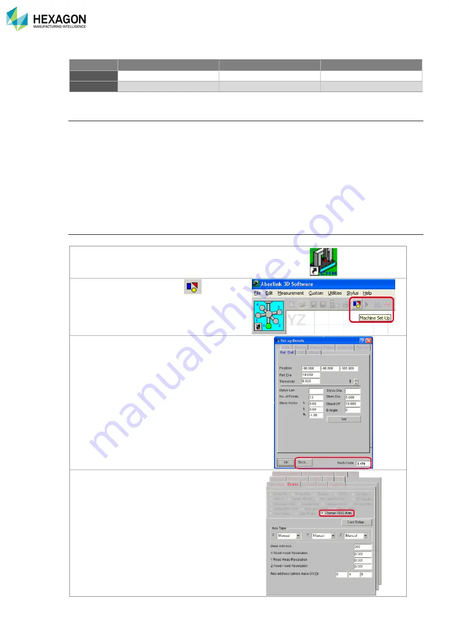
Start Aberlink 3D
Open the ‘Setup’ form (using the
button).
Use the ‘Tech…’ button (code 2.718) to open the
technical details side of the form.
Use the default settings you will need to check
Tab Scales -
set the ‘ROMER RDS Arm’ radio
button.


