Dehumidifier DT 760
34 / 52
EN
The device has been specifically designed for use
on construction sites.
The device must only be operated:
–
for the purpose for which it was intended,
–
in compliance with the instructions in chapter
Assembly, scope of delivery and
accessories
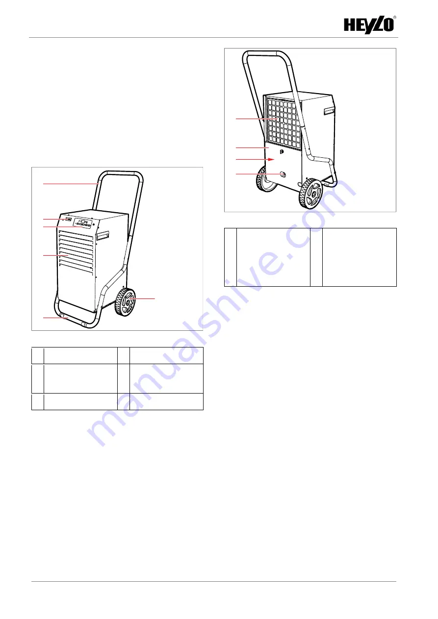
Fig. 11:
Device, front
1 Castors
2 Base bracket
3 Housing with outlet
grille
4 Operating panel
5 Power meter
6 Handle
Fig. 12:
Device, rear
1 Inlet air grille with
filter holder
2 Rear panel
3 Condensate tank
(behind rear panel)
4 Connection for
discharge hose
The scope of delivery includes:
–
Air dehumidifier
–
Filter pad
–
Operating manual
The following device accessories are available:
–
Condensate pump
Mode of operation
The fan draws in humid room air through the inlet
opening. The air flows along the evaporator, where
it cools down. At the evaporator, moisture extract-
ed from the air accumulates in the form of con-
densate. After the room air has been fed along the
evaporator, it is heated in the condenser and
transferred as dry and warm air through the air
outlet to the room. The dried, warm air the ab-
sorbs more moisture from the room.
The condensate produced in the process is fed to
the condensate tank and eventually discharged or
removed by means of an optional condensate
pump.
6
5
4
1
3
2
1
4
2
3
Summary of Contents for 1110588
Page 2: ......
Page 4: ......
Page 29: ...Luftentfeuchter DT 760 DE 27 52 11 4 Schaltplan ...
Page 53: ...Dehumidifier DT 760 EN 51 52 22 4 Circuit diagram ...
Page 54: ......


