COMPUSHIFT II Manual – COMPUSHIFT II Manual
Installation
–
26
•
•
•
•
•
•
•
•
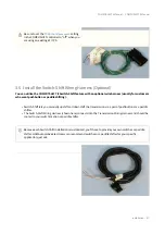
Switch-Shift Connector
(see page 0)
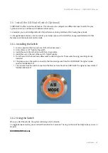
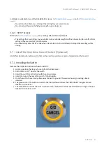
Overdrive Cancel
(see page 0)
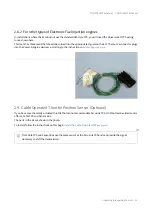
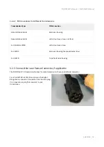
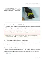
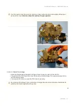
3.3.1 Connect the Throttle Position Sensor
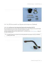
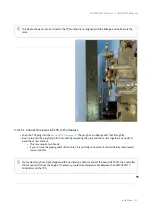
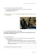
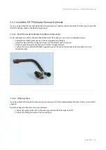
Depending on your engine type, you may have installed an AccuLink TPS, an EFI TPS adapter, or a Cable TPS
system.
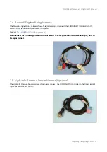
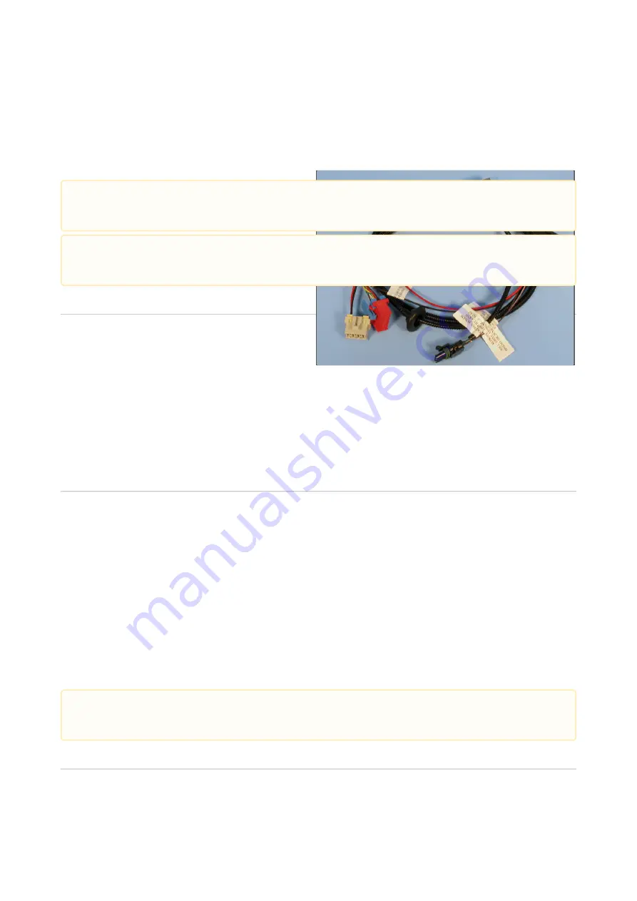
Each of these solutions plugs into the same connector on the Power & Engine Harness.
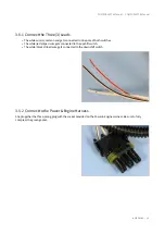
3.3.2 Connect the Power and Meter Leads
Connect the purple/white wire marked "SPEEDOMETER OUT ADJUSTABLE" to the speedometer.
Connect the black wire marked "TO GROUND ON BATTERY OR BLOCK" to a good ground, preferably on the
negative battery terminal or engine block.
Connect the brown wire marked "RPM INPUT TO ECM" to either the tachometer output of an electronic
ignition system (for example, an HEI), or the tachometer output of an MSD ignition system. This will allow
your Display to show your engine RPM.
Connect the red wire marked "TO 12 VOLTS SWITCHED CLEAN SINGLE CIRCUIT" to a circuit (min. 6 amps of
current) that's powered when your ignition switch is turned on.
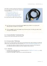
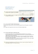
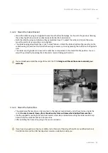
The Power & Engine Harness and its firewall grommet
must
be safely installed. You can re-position the
firewall grommet as needed for your installation.
The harness
must
be routed so that it
never
touches the exhaust system, the rotating drive shaft, or other
moving parts of the drivetrain.
Do
not
connect the tachometer input to the coil of an electronic capacitive discharge (CD) ignition. This
may damage COMPUSHIFT II and void your warranty.


