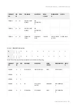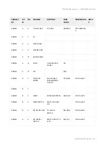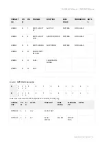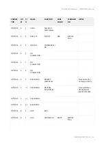
COMPUSHIFT II Manual – COMPUSHIFT II Manual
Specifications & Pinouts
–
97
•
•
•
•
•
•
•
•
•
•
•
•
•
•
•
•
•
•
•
•
•
•
•
•
•
•
•
•
•
•
•
•
•
•
•
•
•
•
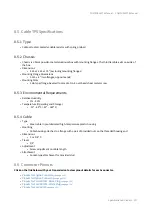
8.2.1.3 Chassis
Chassis is a factory-sealed black powder-coated aluminum box with mounting flanges. There are no user-
serviceable parts inside. The chassis should not be opened.
Dimensions
4.875 x 6.375 x 2.125″ (excluding mounting flanges)
Mounting Flange Dimensions
0.625 x 6.375″ (two flanges, opposite ends)
Mounting Holes
2 – #10 holes per flange
8.2.1.4 Mounting Requirements
Controller must be mounted in a dry area, not exposed to heat from the exhaust, cooling, or heating systems
Controller must have clear air circulation (a 1″ air clearance around the sides and top is recommended)
8.2.1.5 Environmental Requirements
Relative Humidity
0% – 90%, non-condensing
Temperature (Operating)
-30º – 60º C (-22º – 140º F)
Temperature (Storage)
-30º – 85º C (-22º – 185º F)
Protection
Automatic internal shutdown for over-temperature condition
Automatic protection against failed solenoids
8.2.1.6 Electrical Specifications
Supply Voltage
8 – 16 volts DC
Supply Current, Quiescent
600 mA @ 14.4 volts
Supply Current, Maximum
5 A @ 14.4 volts (dependent on transmission type)
Solenoid Capacity
12 solenoids drivers with automatic short-circuit protection
Short- and open-circuit detection with fault reporting
Tachometer Input
High impedance 0 – 12 volt signal input
Tachometer input not required. Used for wide-open throttle upshift and data logging.
Speedometer Input
Designed for variable reluctance inductive pickup on GM and Ford transmissions
Can function with appropriately conditioned 0 – 12 volt signal
Speedometer Outputs
Reproduced OEM TOSS Signal
Variable pulse count per drive shaft revolution
Throttle Position Sensor Input
0 – 5 volt input, filtered against line noise

