HF-A11 Embedded WiFi Module User Manual
Shanghai High-Flying Electronics Technology Co., Ltd
www.hi-flying.com
34
protocol configured as TCP/Client mode, protocol port ID: 8899. Target IP address part setting
the same IP address with left side HF-A11 module (“10.10.100.254” for this example).
When right side HF-A11 boot up, it will find wireless AP (SSID
:
HF-A11_AP for this example)
and open TCP/Client network protocol to connect with left side module’s TCP/Server. All these
operation will be automatic and after finished, the two user devices connected to HF-A11 module
through serial port can communicate each other and think the connection between them is fully
transparent.
3.3.4. Wireless Data Acquisition Card Application
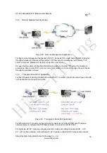
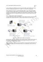
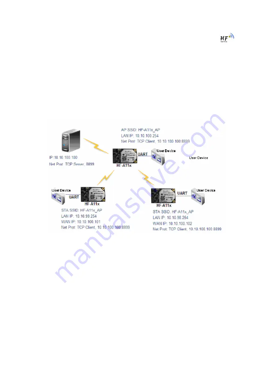
For this wireless data acquisition card application, one PC works as data server and every data
acquisition card connects with a HF-A11 module to support wireless connection function.
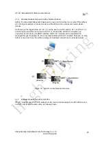
Figure 37. Wireless Data Acquisition Card Application
As above figure, one HF-A11 configured as AP mode and all others configured as STA mode. All
HF-A11 which configured as STA and data server PC wireless connected to HF-A11 which
configured as AP to make up a wires network.
Data server PC open TCP/Server protocol and all HF-A11 modules open TCP/Client protocol. All
data acquisition cards’ data and sampling information can be transmitted to data server PC for
operation.
High-Flying

