background image


Network Protocol:

Use tcp or udp Protocol 

sion within the timeout period, 

e connection will be disconnected. 0 specifies never disconnected. 

6.1


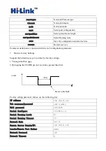
but more than Tes and less than Trst, the module will enter AT instruction mode 

immediately. 


6.2


rate the system parameters through the serial port AT instruction. 


ss as 192.168.11.133. 

r example:"at+remoteip=?\n" Inquiry remote ip address. 

At command is as follows: 


Network Timeout

Under the server network mode, no data transmis

th


6


Serial AT command configuratio

Access to AT command mode 

Module in network fault, such as fault allocation situation will automatically exit the 

transparent transmission mode, enter AT instruction mode. In any condition, keep ES/RST feet low 

level of time 

AT Command 

In AT mode, you can configu

Instruction format is as follows:

  At+[command]=[value]\r 

According to the different command, module will return a different return value. 

For example:"at+remoteip=192.168.11.133\n" set remote ip addre

Fo


ver 

The version of module 

remoteip 

Remote server domain name or IP address 

remoteport 

The local or distal port number 

>Tes 

<Trst 


AT Command 

ES/RST


Summary of Contents for HLK-RM04

Page 1: ...HLK RM04 User Manual ETHERNET WIFI Full Function Serial Network Wireless Module...

Page 2: ...ORK PARAMETER 6 4 PARAMETER CONFIGURATION DIRECTION 6 5 WEB CONFIGURATION 7 5 1 WEB NETWORK CONFIGURATION 7 5 2 WEB SERIAL CONFIGURATION 7 6 SERIALAT COMMAND CONFIGURATION 8 6 1 ACCESS TO AT COMMAND M...

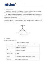
Page 3: ...configuration data can be transmitted through the Internet network Provide a quick solution for the user s serial devices to transfer data via Ethernet Picture1 F structure 2 Summarize 2 1 Technical...

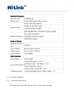
Page 4: ...B software upgrade Serial to Network Maximum transmission rate 230400bps TCP connection Max connection number 20 UDP connection Max connection number 20 Serial baud rate 50 230400bps Other Parameters...

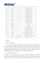
Page 5: ...ction Direction Explanation 1 VCC5V A Supply Voltage 5V 10 2 GND GND Analogue Ground 3 WIFILED O WLAN Activity LED 4 VO3 3 I 3 3V Output Suuport Atmost 300mA 5 LINK1 I O 10 100 PHY Port 1 activity LED...

Page 6: ...In Supply Voltage 5V 10 3 Quick Start 3 1 Restore factory settings In order to ensure that all of configuration process is correct bringing the module to restore the factory settings firstly Factory...

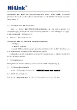
Page 7: ...guration direction The module provides two ways for the configuration parameters 1 Web page 2 Serial AT command Access to WEB configuration page requires the confirmation of the module s IP addresses...

Page 8: ...he Lenth of Serial Framing rial Framing Timeout The time of Serial Framing twork Mode choose Client Server or none ess r exmpale 192 168 11 245 or www hlktech com pa Serial bit Fo Se Se Ne Remote Serv...

Page 9: ...ata transmis th 6 Serial AT command configuratio Access to AT command mode Module in network fault such as fault allocation situation will automatically exit the transparent transmission mode enter AT...

Page 10: ...e factory settings By keeping the ES RST pin low level time greater than Trst parameter values see the following 4 7 Restore factory Settings Support the following way 1 Through the Web page 2 Factory...

Page 11: ...Select the appropriate firmware click apply upgrades Wait a 9 on will give some simple examples to use the different functions of a typical 6 123 255 255 255 0 Browser ADIO OFF button to turn off wif...

Page 12: ...ou to modify the the LAN port parameters Set Ethernet ip address gateway dns server information click apply to take effect 5 At this moment you must use new ip address to access the web page 9 1 Seria...

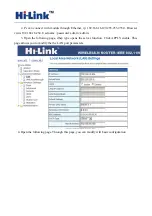
Page 13: ...wser visits 192 168 16 254 Username password admin admin 3 Open the following page dhcp type opens the server function Click APPLY enable This page allows you to modify the the LAN port parameters 4 O...

Page 14: ...odify the wifi security related function You can modify the wifi key Clicks APPLY to take effect 6 At this point connected to the module by other wifi devices Module IP 192 168 16 254 9 2 Serial to wi...

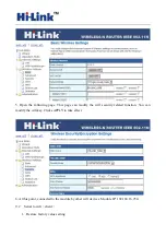
Page 15: ...o 192 168 16 254 Username password admin admin 3 Open the following page set to Ethernet Converter mode Click on the APPLY to take effect 4 Open the following page Click APPLY to increase AP informati...

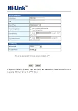
Page 16: ...6 Open the following page This page can modify the WiFi security related function You can modify the WiFi key Click on the APPLY effect...

Page 17: ...7 Open the following page view IP information of the module Wan IP address is the ip If no IP address appears it means disconnected to AP...

Page 18: ...Appendix A document revision record Version number Revision range Date 1 00 Draft version 2012 9 10...

Reviews: