background image

3

HLK-RM08S

2.1. Typical application

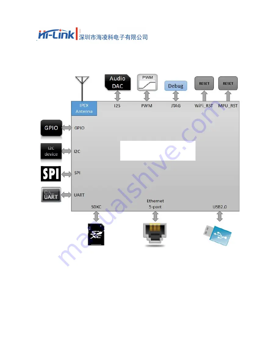
HLK-RM08S typical peripheral interfaces diagram

HLK-RM08S

Summary of Contents for HLK-RM08S

Page 1: ...SHENZHEN HI LINK ELECTRONIC CO LTD HLK RM08S USER MANUAL Version V1 0 Issuing date 2017 2 17 copy right Hi Link...

Page 2: ...TION 3 2 2 SPECIFICATIONS 4 3 ELECTRICAL CHARACTERISTICS 4 3 1 INPUT VOLTAGE 4 3 2 RF CHARECTERISTICS 5 3 2 1 802 11B 11M 5 3 2 2 802 11G 54M 5 3 2 3 802 11N MCS7 HT20 6 3 2 4 802 11N_MCS7 HT40 6 4 PI...

Page 3: ...parameters High data processing ability MCU frequency 580MHz 150M Mbps Support 802 11b g n mode 20 40 channel bandwidth Support 802 11v Support AP STA and AP STA mixed Fifth 10 100M adaptive com port...

Page 4: ...2 HLK RM08S 2 Block diagram HLK RM08S Block Diagram EINT Ethernet UART GPIO PWM USB_HOST SPI SPIS I2C I2S JTAG SDXC MT7688KN 3 3V 40MHz SPI Flash 32MB IPEX Connector...

Page 5: ...3 HLK RM08S 2 1 Typical application HLK RM08S typical peripheral interfaces diagram HLK RM08S...

Page 6: ...b Flash 32Mb RF 1T1R 802 11n 2 4GHz USB2 0 1 UART 2 Temperature Environmental temperature 40 85 Humidity working 10 95 noncondensing Storage 5 95 noncondensing Size 17 4mm 25 8mm 2 8mm 3 Electrical ch...

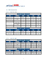
Page 7: ...802 11b Receiver Conductive Item Condition Min Typ Max Unit Frequency Range Channel 1 Channel 13 Min Input 11Mbps PER 8 91 5 89 5 87 5 dBm 3 2 2 802 11g 54M 802 11g Transmit Conductive Item Condition...

Page 8: ...ndition Min Typ Max Unit Frequency Range Channel 1 Channel 13 Min Input MCS7 PER 10 76 5 74 5 72 5 dBm 3 2 4 802 11n_MCS7 HT40 802 11n_HT40 Transmit Conductive Item Condition Min Typ Max Unit Frequenc...

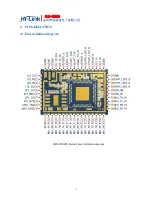
Page 9: ...7 HLK RM08S 4 PINS DEFINTION 4 1 Pins definition diagram HLK RM08S Default pins definition diagram...

Page 10: ...rial port TR 11 GPIO0 REF_CLKO PERST_N GPIO11 12 MDI_RP_P0 GPIO24 13 MDI_RN_P0 GPIO23 14 MDI_TP_P0 GPIO22 15 MDI_TN_P0 GPIO21 16 MDI_TP_P1 SPIS_CS PWM_CH0 GPIO14 17 MDI_TN_P1 SPIS_CLK PWM_CH1 GPIO15 1...

Page 11: ...JTAG_TDO GPIO34 Com 0 status led 37 GND 38 GND 39 3 3V Suggested external power supply current 500mA 40 3 3V 41 WLED_N GPIO35 WiFi status LED 42 EPHY_LED1 JTAG_TDI GPIO33 Com 1status LED 43 EPHY_LED3...

Page 12: ...space 1 4mm depth 1 8mm 2 The thickness of the module is 1 8mm 3 The noted numbers in the picture is the actual size of module do recommended pad extension around 1mm internal heat shrink 0 2mm pad i...

Page 13: ...fixed device is defined as a device is physically secured at one location and is not able to be easily moved to another location Note 2 Any modifications made to the module will void the Grant of Cert...

Page 14: ...Note 6 FCC ID label on the final system must be labeled with Contains FCC ID 2AD56HLK RM08S or Contains transmitter module FCC ID 2AD56HLK RM08S...

Reviews: