background image


User Manual


- 12 - 


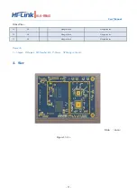
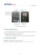
Figure 4 Module interface description 


5.


Indicator light description


2G/5G wifi  indicator  light: After  turning  on  the  wifi  function,  the  module  wifi  indicator  will  flash,  after 

turning off the wifi indicator, the module

s wifi indicator will go out. 

Pwr indicator: power indicator, always on when power on. 

Network port indicator: After plugging in the network cable, the corresponding LED indicator will flash. 


6.


Pin function description


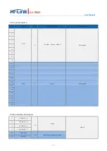
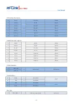
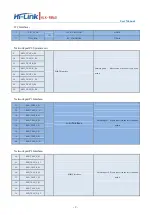
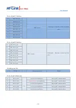
D2DB_PORST_N

Hardware reset pin

Pull down  time

≥100ms


WDT_RST_N

Software reset pin

Pull down time

≥6000ms

The system will be


restarted


Wifi Light 

Fixing hole 

5.8G wifi Ant 


2.4G wifi Ant 

Network&Power light 

Connect port 

Summary of Contents for HLK-RM60

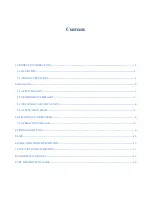
Page 1: ...Shenzhen Hi Link Electronic CO Ltd HLK RM60 User Manual...

Page 2: ...PECIFICATION 3 2 2 NUMBER OF INTERFACES 3 2 3 TECHNICALSPECIFICATIONS 4 2 4 APPLICATION FIELD 5 3 ELECTRICALPARAMETERS 5 3 1 OPERATINGVOLTAGE 5 4 PIN INTRODUCTION 6 5 SIZE 12 6 INDICATOR LIGHT DESCRIP...

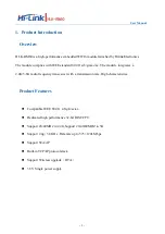
Page 3: ...e integrates a 2 4G 5 8G radio frequency transceiver with a transmission rate Highcharacteristics Product Features Compatible IEEE 802 11 a b g n ac ax Dedicated high performance 32 bit RISC CPU Suppo...

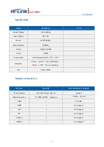
Page 4: ...ent temperature 20 60 Humidity Using 10 95 Non condensing Stock 5 95 Non condensing Size 90mm 60mm Number of interfaces Interface Quantity Default firmware Support WiFi Standard IEEE 802 11b g n a ac...

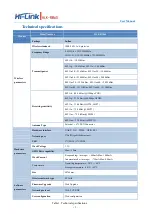
Page 5: ...ps CCK 802 11g 75 7dBm 54Mbps OFDM 802 11n 73 6dBm HT20 MCS7 802 11a 75 0 dBm MCS7 802 11ac 75 0 dBm MCS9 802 11ax 73 0 dBm MCS11 Antenna Type External 4 I PEX Connector Hardware parameters Hardware i...

Page 6: ...otection and security Smart card terminals wireless POS machines handheld devices etc 2 Electrical parameters Working voltage Parameter Smallest Typical Max Unit Working voltage 3 3 3 3 6 V I O Voltag...

Page 7: ...User Manual 5 3 Pin introduction Figure 2 Module pin sorting...

Page 8: ..._TXVN_C_P4 15 SSUSB_TX_N 16 ESW_TXVP_C_P0 53 ND_CLE 54 ESW_TXVN_C_P2 91 ESW_P0_LED 92 ESW_TXVP_D_P4 17 SSUSB_RX_P 18 ESW_TXVN_C_P0 55 ND_WE_N 56 ESW_TXVP_D_P2 93 3 3VD 94 ESW_TXVN_D_P4 19 SSUSB_RX_N 2...

Page 9: ...1 3 3VD P 3 3VInput Current 1500mA Power Supply 3 5 7 9 93 95 97 99 2 GND P Ground Power Supply 4 6 11 21 24 42 60 78 96 98 100 USB3 0 Interface Description 13 SSUSB_TX_P I O USB3 0 USB3 0 15 SSUSB_TX...

Page 10: ...SD_WP GPIO 41 45 ND_RB_N SD_CLK GPIO 42 57 ND_ALE SD_CMD GPIO 44 53 ND_CLE SD_CD GPIO 43 43 ND_D0 SD_DATA0 GPIO 45 41 ND_D1 SD_DATA1 GPIO 46 39 ND_D2 SD_DATA2 GPIO 47 37 ND_D3 SD_DATA3 GPIO 48 USB2 0...

Page 11: ...20 ESW_TXVP_D_P0 22 ESW_TXVN_D_P0 Network port P1 Interface 26 ESW_TXVP_A_P1 PORT1 Interface Network port 1 Please leave it in the air if youdon t need it 28 ESW_TXVN_A_P1 30 ESW_TXVP_B_P1 32 ESW_TXV...

Page 12: ..._B_P4 86 ESW_TXVN_B_P4 88 ESW_TXVP_C_P4 90 ESW_TXVN_C_P4 92 ESW_TXVP_D_P4 94 ESW_TXVN_D_P4 Watchdog resetPin 81 WDT_RST_N I Function pin activelow GPIO 18 Network port indicator pin 83 ESW_P4_LED I O...

Page 13: ...er Pins 59 NC Hang in the air Hang in the air 79 NC Hang in the air Hang in the air 27 NC Hang in the air Hang in the air Remark 1 I Input O Output I O Number I O P Power NCHang in the air 4 Size Unit...

Page 14: ...s wifi indicator will goout Pwr indicator power indicator always on when power on Network port indicator After plugging in the network cable the corresponding LED indicator will flash 6 Pin function...

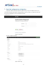
Page 15: ...the module s LAN port open the computer browser enter 192 168 16 254 and you will enter the web login interface enter the user name root password admin and then click the Login button to enter the con...

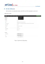
Page 16: ...User Manual 14 8 Set the wifi name After entering the web configuration interface click WIFI select WIFI configuration enter thewifi configuration interface Figure 7 Enter the wifi setting interface...

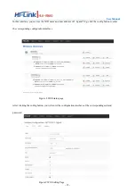
Page 17: ...c address of 2 4g and 5 8g click the config button toenter the corresponding configuration interface Figure 8 Wifi Statuspage After clicking the config button you will enter the configuration interfac...

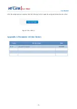
Page 18: ...he configuration is completed click the following button to make the configured information take effect Figure 10 Save Button Appendix A Document revision history Version Revision scope Date V1 0 Orig...

Page 19: ...Installation Manual List of applicable FCC rules This module has been tested and found to comply with part 15 247 and part 15 407 requirements for Modular Approval Summarize the specific operational...

Page 20: ...hat the final composite product complies with the FCC requirements by a technical assessment or evaluation to the FCC rules including the transmitter operation and should refer to guidance in KDB 9963...

Reviews: