background image

20

The OEM integrator is responsible for ensuring that the host product which is installed and
operating with the module is in compliant with Part 15B unintentional Radiator requirements,
please note that For a Class B digital device or peripheral, the instructions furnished the user
manual of the end-user product shall include the following or similar statement, placed in a
prominent location in the text of the manual:
Note: This equipment has been tested and found to comply with the limits for a Class B digital
device, pursuant to part 15 of the FCC Rules. These limits are designed to provide reasonable
protection against harmful interference in a residential installation. This equipment generates, uses
and can radiate radio frequency energy and, if not installed and used in accordance with the
instructions, may cause harmful interference to radio communications. However, there is no
guarantee that interference will not occur in a particular installation. If this equipment does cause
harmful interference to radio or television reception, which can be determined by turning the
equipment off and on, the user is encouraged to try to correct the interference by one or more of the
following measures:

Reorient or relocate the receiving antenna.

Increase the separation between the equipment and receiver.

Connect the equipment into an outlet on a circuit different from that to which the receiver is

connected.

Consult the dealer or an experienced radio/TV technician for help.

OEM Installation Guidance Document

FCC ID: Z4T

-WM7628N-A

Conditions on using Seeed regulatory approvals:
A. Customer must ensure that its product (the

CUSTOMER Product

) is electrically identical to

Seeed reference designs. Customer acknowledges that any modifications to Seeed reference designs
may invalidate regulatory approvals in relation to the CUSTOMER Product, or may necessitate
notifications to the relevant regulatory authorities.
B. Customer is responsible for ensuring that antennas used with the product are of the same type,
with same or lower gains as approved and providing antenna reports to Seeed.
C. Customer is responsible for regression testing to accommodate changes to Seeed reference
designs, new antennas, and portable RF exposure safety testing/approvals.
D. Appropriate labels must be affixed to the CUSTOMER Product that comply with applicable
regulations in all respects.

Summary of Contents for WM7628N-A

Page 1: ...1 SHENZHEN HI LINK ELECTRONIC CO LTD WM7628N A User Manual...

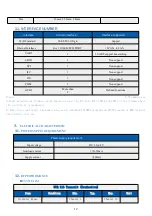
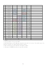
Page 2: ...L CHARACTERISTIC 12 3 1 POWER SUPPLY REQUIREMENT 12 3 2 RF PERFORMANCE 12 802 11B 11M 12 802 11G 54M 13 802 11N MCS7 HT20 13 802 11N_MCS7 HT40 14 4 MODULE PINS DEFINITION 14 4 1 DEFAULT PIN DEFINITION...

Page 3: ...at the same time it also support secondary development 1 1 BASIC PARAMETER High data processing ability MCU frequency 580MHz 300M Mbps Support 802 11b g n 20 40 Channel bandwidth Support 802 11v Suppo...

Page 4: ...Basic frequency 580MHz RAM DDR2 128MB Customizable DDR2 64M 32MB Flash 32MB Customizable 16MB 8MB Temperature Environment temperature 40 85 Humidity Working 10 95 noncondensing Storage 5 95 nonconden...

Page 5: ...e module was default embedded our firmware which based on Linux the Ethernet WiFi UART0 and UART1 of the firmware have the function of transmission 2 Based on actual usage the module also can be embed...

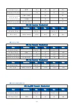
Page 6: ...54M 802 11g Transmit Conductive Item Condition Min Typ Max Unit Frequency Range Channel 1 Channel 13 Tx Power Level OFDM 15 17 19 dBm Frequency Tolerance 15 0 15 ppm Modulation Accuracy All Data Rate...

Page 7: ...Max Unit Frequency Range Channel 1 Channel 13 Tx Power Level OFDM 15 0 17 0 19 0 dBm Frequency Tolerance 15 0 15 ppm Modulation Accuracy All Data Rate 31 28 dB 802 11n_HT40 Receiver Conductive Item C...

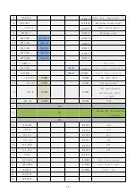
Page 8: ...smission 16 UART_RXD1 PWM_CH1 GPIO 46 Port 1 date reception 17 I2S_SDI PCMDRX GPIO 0 I2S date input 18 I2S_SDO PCMDTX GPIO 1 I2S date output 19 I2S_WS PCMCLK GPIO 2 I2S sound channel selection 0 left...

Page 9: ...47 MDI_TN_P3 SD_CD eMMC_CD GPIO 23 48 MDI_RP_P3 SD_D1 eMMC_D1 GPIO 24 49 MDI_RN_P3 SD_D0 eMMC_D0 GPIO 25 50 MDI_RP_P4 SD_CLK eMMC_CLK GPIO 26 51 MDI_RN_P4 SD_CMD eMMC_CMD GPIO 28 52 MDI_TP_P4 SD_D3 eM...

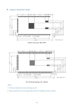
Page 10: ...CHART Module dimension chart TOP Recommended package size diagram Notes 1 The three intermediate pads are hot pads please ground 2 Package pad epitaxial size can be appropriately shortened or lengthen...

Page 11: ...European label text version eVatmaster Consulting GmbH Bettinastr 30 60325 Frankfurt am Main Germany contact evatmaster com 6 2 7 2European label picture format for reference only you can design acco...

Page 12: ...el can use wording such as the following Contains FCC ID Z4T WM7628N A any similar wording that expresses the same meaning may be used RF Exposure Compliance This equipment complies with FCC radiation...

Page 13: ...e equipment off and on the user is encouraged to try to correct the interference by one or more of the following measures Reorient or relocate the receiving antenna Increase the separation between the...

Page 14: ...ns However there is no guarantee that interference will not occur in a particular installation If this equipment does cause harmful interference to radio or television reception which can be determine...

Page 15: ...odes and additional testing requirements OEM manufacturer should perform additional verification validation on supported modes and is responsible for validation testing of module host The final system...

Reviews: