background image

                                         i

RTK5 Smart GNSS System User Manual 

30


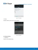
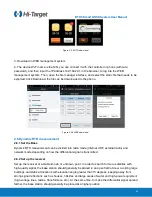
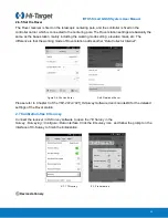
Figure 2-5-4 OTG download 


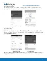
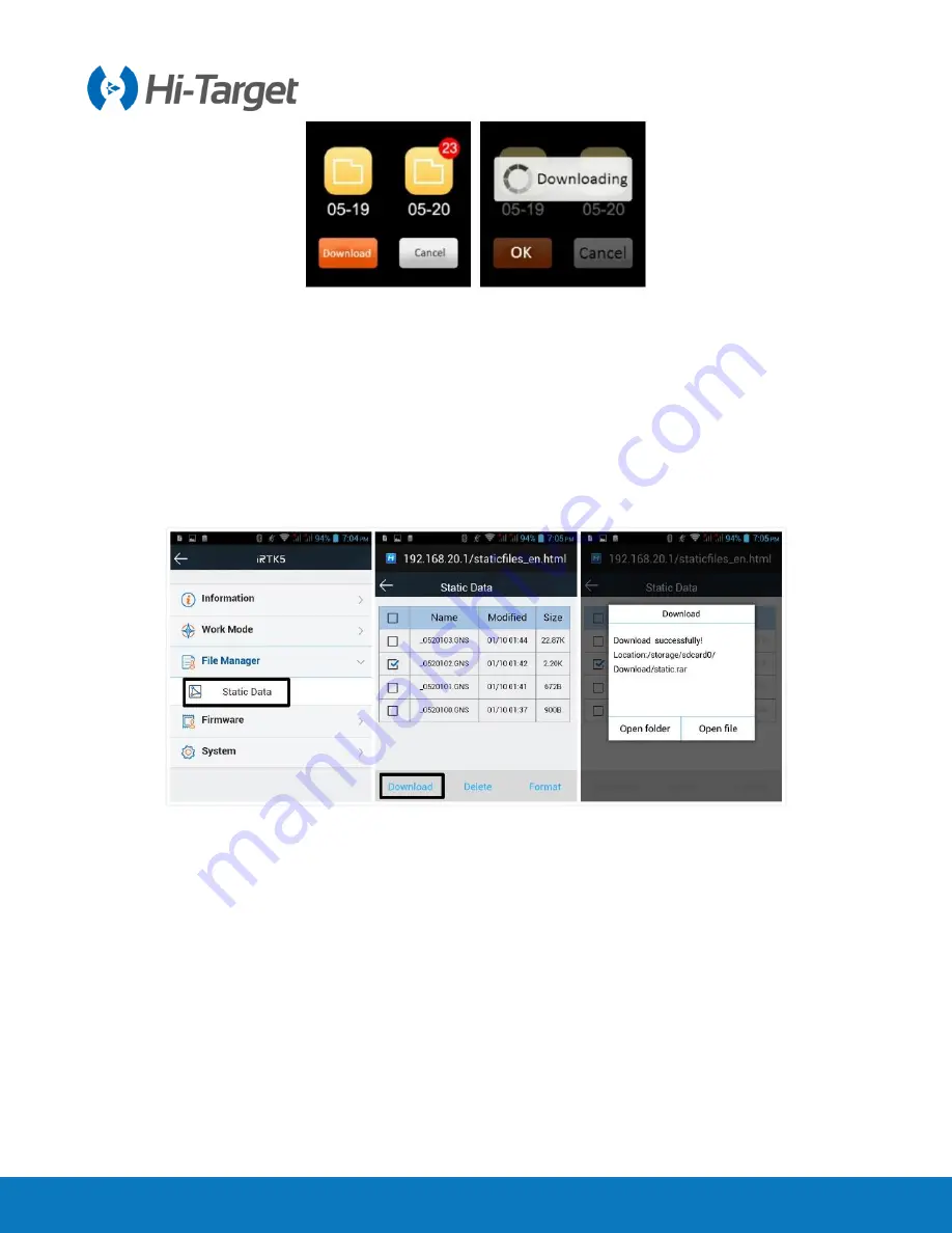
3. Download in WEB management system 

4. The device Wi-Fi name is the S/N, you can connect it with the controller or phone (without a 

password), and then input the IP address 192.168.20.1 in the browser, to log into the WEB 

management system. Then, open the file manager interface, and select the static file that needs to be 

exported. Click Download, the file can be downloaded to the phone. 


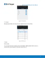
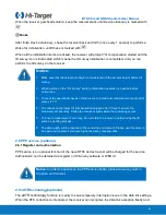
Figure 2-5-5 WEB download 

2.6 Dynamic RTK measurement 

2.6.1 Set the Base 

Dynamic RTK measurement can be divided into radio mode (internal UHF, external radio) and 

network mode depending on how the differential signal is transmitted. 

2.6.2 Set up the receiver 

Set up the receiver at a stable known or unknown point. In order to search for more satellites with 

high-quality signal, the base station should generally be placed in an open field of view, avoiding large 

buildings and slabs at locations with elevation angle greater than 15 degrees, keeping away from 

strong signal reflections such as houses, hillsides and large areas of water and high-power equipment 

(high-voltage lines, radios, transformers, etc.). At the same time, to make the differential signal spread 

farther, the base station should generally be placed at a higher position. 

Summary of Contents for iRTK5

Page 1: ...iRTK5 Smart GNSS RTK System User Manual ...

Page 2: ...iRTK5 Smart GNSS System User Manual Revision Date Revision Level Description Mar 2018 1 iRTK5 GNSS RTK System User Guide A1 July 2019 2 iRTK5 GNSS RTK System User Guide A2 ...

Page 3: ...iRTK5 Smart GNSS System User Manual iRTK5 Smart GNSS RTK System User Manual ...

Page 4: ...even break the system and endanger your safety Exclusions Before using the product please read these operating instructions carefully they will help you to use it better Hi Target Surveying Instrument Co Ltd assumes no responsibility if you fail to operate the product according to the instructions or operate wrongly due to misunderstanding the instructions Hi Target is committed to constantly perf...

Page 5: ...troduction by 1 After purchasing Hi Target products you will find this manual in the instrument container to guide you on operating the instrument 2 Log onto the Hi Target official website download the electronic version introduction at Partners Partner Center Advice If you have any suggestions for this product please email info hi target com cn Your feedback information will help us to improve th...

Page 6: ...9 Product Introduction 9 2 1 Hardware structure 10 2 1 1 Upper cover 10 2 1 2 Bottom cover 11 2 1 3 Control panel 12 2 2 Button LED 12 2 2 1 Button 12 2 2 2 LED 13 2 3 Touch screen display 13 2 3 1 Status interface 13 2 3 2 Stand by interface 15 2 3 3 Settings interface 16 2 4 Web management system 17 2 4 1 Main menu 17 2 4 2 Information view 19 2 4 3 Work mode 21 2 4 4 File management 23 2 4 5 Fi...

Page 7: ...gy optional 33 2 10 Firmware upgrade 34 2 10 1 Upgrade by USB cable 34 2 10 2 Upgrade by OTG and USB flash disk 34 2 10 3 Upgrade by WEB management system 34 2 10 4 Remote online upgrade 34 Chapter 3 36 Technical parameters 36 Chapter 4 400 Interfaces and Accessories 40 4 1 SIM card installation 41 4 2 Data cable 41 4 3 Antenna 42 4 4 Benchmark 42 4 5 Battery charger 42 Chapter 5 44 iHand30 Contro...

Page 8: ... cable 49 5 3 4 Touch pen 50 5 4 Operation 50 5 4 1 Keyboard 50 5 4 2 Battery installation and dis assembly 51 5 4 3 Power system 54 5 4 4 SIM card setting 55 5 4 5 Installation of the Micro SD card 57 5 4 6 Power on off 58 5 5 Application 59 5 5 1 Connecting the controller to computer 59 5 5 2 Upgrade method 61 ...

Page 9: ...iRTK5 Smart GNSS System User Manual 6 Chapter 1 Overview This chapter contains Foreword Features ...

Page 10: ...on and multiple channels with Maxwell7 technology and four star tri band solution providing the position quickly and reliably 3 It supports the PPP service optional There is no need to set up a base station or connect CORS to achieve accurate real time centimeter level positioning of stand alone 4 It supports aXTR technology making measurement more continuous and reducing wait time 5 It supports t...

Page 11: ...he LED 13 Stronger with innovative designs and a magnesium alloy structure 14 Double format storage of static data GNS RINEX 15 With the new generation controller iHand30 it supports 4G WiFi OTG quick charge and so on 16 HDL multi protocol radio compatible with imported brands supports external radio network relay and radio relay 17 With the new Hi Survey software with new UI it supports multiple ...

Page 12: ... Chapter 2 Product Introduction This chapter contains Hardware structure Button LED Touch display Web management system Static measurement Real Time Kinematic RTK surveying Tilt survey PPP service optional aXTR technology Firmware upgrade ...

Page 13: ...enna interface connect the radio antenna while using the built in radio mode When using the built in network mode in a poor signal network environment you can use the antenna interface to connect the external 4G antenna the iRTK5 has built in 4G antenna but you need to use the external 4G antenna in a poor signal network environment and choose the external antenna mode when using Hi Survey softwar...

Page 14: ...s to upgrade firmware and download static data It can also be used as the USB to serial port in special working modes you need to install the driver It supports OTG Five pin socket for external data linking and external power supply Connection screw for fixing the instrument to the base or a pole Battery compartment cover dustproof and waterproof 5 1 2 3 4 6 1 USB socket 2 Power light button 3 Fiv...

Page 15: ...trol panel 2 2 Button LED 2 2 1 Button Table 2 2 1 Button function description Function Description Power on Press the button for 1 second Power off Press the button for at least 3 seconds LCD display switch Double click the power button to open or close the LCD display Forced shutdown Execution in case of crash Press the power button for at least 12 seconds Check the current status Click the powe...

Page 16: ...mode Sampling interval 1S flash at the sampling interval Sampling interval 1S flash once per second Off 1 RTK mode no differential data 2 Static mode sampling has not started Satellite LED Long term lighting Satellite tracked Flash Satellite not tracked 2 3 Touch screen display The receiver has a 1 3 inch 240 240 high resolution touch screen to support touch operation Double click the power button...

Page 17: ... status of the network Connected to network Displays in a cycle with the differential data format and current power External radio base Displays in a cycle with the differential data format and current power Internal UHF rover Shows the solution status Internal GSM rover Unconnected to network Shows the status of the network Connected to network Shows the solution status External radio rover Shows...

Page 18: ...ration for more than 60s and then turn off after 5 minutes Double click the power button or click the screen to resume the LCD display and show the status Table 2 3 2 Stand by screen Icons Description Shows the external power supply icon and local time when using the 5 pin such as on external device base mode Only shows the power icon when not tracked Shows the power icon and local time when using...

Page 19: ... the Stop two choices OK and Cancel and you can click OK to stop and return to the interval settings interface Reset Click Reset in setting interface to reset the motherboard after click OK there will be the pop up window displaying Resetting If success the LCD display Reset motherboard successful and it will jump to the status interface after 2 seconds If failed the LCD displays Reset motherboard...

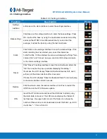
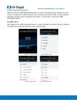
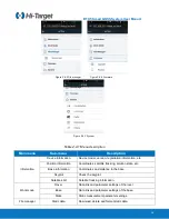
Page 20: ...ect it with the controller or phone without a password and then input the IP address 192 168 20 1 in the browser to log into the WEB management system 2 4 1 Main menu After logging into the WEB management system you can click Start to enter the main menu interface The main menu contains the drop down menu with each option Figure 2 4 1 Welcome page Figure 2 4 2 Main menu Figure 2 4 3 Information Fi...

Page 21: ...information etc Position information Coordinates satellite tracking solution state etc Base information Coordinates and distance to the base Skyplot Check the skyplot Satellites list Satellite tracking information Work mode Rover Data link and parameter settings of the rover Base Data link and parameter settings of the base Static Static measurement parameter settings File manager Static data Down...

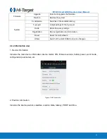
Page 22: ...ency settings Registration Device registration and information Reset Reset the motherboard Others Switch of the static RINEX and voice changes 2 4 2 Information view 1 Device information Includes the main device information device model S N firmware version battery power work mode configuration parameters etc Figure 2 4 8 Device info 2 Position information Includes the device position satellites s...

Page 23: ...l 20 Figure 2 4 9 Position info 3 Base information Includes the coordinates and distance of the base when in the rover mode Figure 2 4 10 Base info 4 Sky plot Includes the sky plot with the ability to switch to different constellations ...

Page 24: ...t 5 Satellites list Shows the satellites tracked information Figure 2 4 12 Satellites list 2 4 3 Work mode 1 Rover Set up the data link and parameters of the rover Rover station data link mode includes Internal UHF Internal GSM External and PPP optional function ...

Page 25: ...rs of the base and get the point coordinates by averaging The base data link mode includes Internal UHF Internal GSM and External radio Figure 2 4 14 Base 3 Static Set up the file name and parameters of the static collection Note after ticking Static Mode you can only cancel in the Base or Rover mode ...

Page 26: ...w static data files it supports Download and Delete options Figure 2 4 16 Static data 2 4 5 Firmware management 1 Upgrade Display specific device version information Click Select choose the upgrade package then click Start Upgrade the receiver will automatically detect the upgrade package and upgrade ...

Page 27: ...Smart GNSS System User Manual 24 Figure 2 4 17 Upgrade 2 Restore Restart the iRTK5 and do the OTA firmware update Figure 2 4 18 Restore 2 4 6 System settings 1 Constellation Switches of the satellite tracking ...

Page 28: ... 5 pin port Message type switches and output frequency adjustments 1Hz 2Hz and 5Hz Figure 2 4 20 5 pin port 3 Radio Radio module You can select the radio modulation protocol HI TARGET TRIMTALK450S SOUTH CHC to customize the channel frequency of the radio channel 100 115 ...

Page 29: ... Smart GNSS System User Manual 26 Figure 2 4 21 Radio 4 Registration Includes registration information serial number etc Provides online registration Figure 2 4 22 Registration 5 Reset Reset the motherboard ...

Page 30: ...Figure 2 4 24 Others 2 5 Static mode 2 5 1 Static settings There are three ways to set up the device to work in the static mode 1 LCD Static settings to set up static mode 2 Hi Survey software Static interface to set up static or temporary static mode 3 WEB Interface Work Mode to set up static or temporary static mode ...

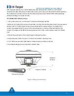
Page 31: ...height of the receiver three times ensuring that the difference of each measurement is less than 3mm The final height of the receiver should be the average height The height of the receiver is measured from the center of the measuring point to the top of the benchmark of the receiver The radius of the iRTK5 receiver benchmark is 0 130m and the phase center is 0 0790m high 3 Record the point name S...

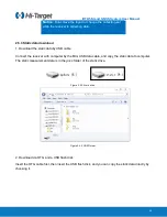
Page 32: ...a by USB cable Connect the receiver with computer by the Mini USB data cable and copy the static data to computer The static measurement data is in the gnss folder of the static drive Figure 2 5 2 Static drive Figure 2 5 3 GNSS folder 2 Download via OTG and a USB flash disk Insert the OTG cable first then insert the USB flash disk and you can copy the static data directly by choosing it ...

Page 33: ...rement can be divided into radio mode internal UHF external radio and network mode depending on how the differential signal is transmitted 2 6 2 Set up the receiver Set up the receiver at a stable known or unknown point In order to search for more satellites with high quality signal the base station should generally be placed in an open field of view avoiding large buildings and slabs at locations...

Page 34: ...s include setting the height of the target coordinates working mode and corresponding parameters correction type elevation mask etc After completing the parameter settings click the Set button in the upper right corner and the software prompts Base station is ready do you want to set Rover now Figure 2 6 3 Set the Base 2 6 4 Datalink of Base Please refer to Chapter 3 of the YFZ 2014 1925_Hi Survey...

Page 35: ...at the working mode of Rover station adds another Data Collector Internet Figure 2 6 3 Set the Rover 2 6 4 Datalink of Rover Please refer to Chapter 3 of the YFZ 2014 1925_Hi Survey Software User s Guide B8 for the detailed settings of the Rover station 2 7 Calibration free tilt survey Connect the receiver in Hi Survey software to open the Tilt Survey in the Survey Surveying Configure Data interfa...

Page 36: ...t angle of tilt survey is 70 4 The receiver will prompt Tilt compensation stopped after 30 sec to ensure the measurement accuracy Shake the receiver slightly when the prompting occurs 5 To ensure measurement accuracy do not rotate the receiver quickly during the tilt survey s working process 6 The data quality will be reduced in the occlusion environment Please use tilt survey in an open environme...

Page 37: ...ll be different prompt voices of upgrade successes or failures If it fails please contact our technical team Figure 2 10 1 Update drive 2 10 2 Upgrade by OTG and USB flash disk Copy the firmware to the USB flash disk and connect the USB disk to the receiver with the OTG cable When the prompt voice asks to upgrade or not click Yes 2 10 3 Upgrade by WEB management system Copy the firmware to the con...

Page 38: ...irmware to complete it Or click Device Check Update in Hi Survey software to check it Notice 1 After the download failed if the network recovers within two minutes it will resume downloading otherwise it will exit the firmware upgrade detection 2 It is not allowed to forcibly power off during the upgrade If the power is forcibly cut off the instrument may be damaged and the instrument may be abnor...

Page 39: ...iRTK5 Smart GNSS System User Manual 36 Chapter 3 Technical parameters This chapter contains Technical parameters ...

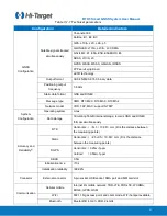
Page 40: ...AC support NTRIP System Configuration Operating system Linux Data storage Circulating 16GB internal storage records GNS and RINEX formats simultaneously Accuracy and Reliability 1 RTK Horizontal 8 1 10 6D mm D is the distance between the measuring points Static Horizontal 2 5 0 5 10 6D mm D is the distance between the measuring points DGPS Horizontal 0 25m 1ppm Vertical 0 50m 1ppm SBAS 0 5m Initia...

Page 41: ...g rod and compensate to correct the coordinates Built in high precision inertial navigation automatic attitude compensation no need for correction anti magnetic interference and accuracy is 2 3 cm within 30 degrees Temperature sensor Intelligent temperature control User Interface Button Single button Touch screen Industrial OLED color screen 240 240 capacitive touch waterproof supports glove opera...

Page 42: ...re 40 75 Storage temperature 50 85 Notice 1 Measurement accuracy and reliability are affected by many factors including the satellite s geometric distribution number of satellites observation time satellite ephemeris ionospheric conditions and multipath 2 Tilt measurement accuracy is disturbed by many factors including external electromagnetic interference pre calibration precautions and panel ori...

Page 43: ...ories This chapter contains SIM card installation Data cable Antenna Benchmark Battery charger 4 1 SIM card installation iRTK5 receiver supports Nano SIM card the SIM card installation method is as follows 1 Remove the battery cover and battery exposing the SIM card slot ...

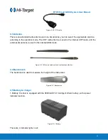
Page 44: ...SIM card installation 4 2 Data cable 1 Mini USB data cable to connect the iRTK5 host and the computer to upgrade the firmware and download static data Figure 4 2 1 Mini USB data cable 2 Five pin data cable DG 3 to connect the host and external radio to transmit differential data Figure 4 2 2 Five pin data cable 3 OTG cable for USB flash disk s OTG firmware upgrade and static data download ...

Page 45: ...d in the internal UHF mode and the external 4G antenna is used in the internal GSM mode Figure 4 3 1 4G antenna above and radio antenna below 4 4 Benchmark The benchmark is used to measure the height of the instrument Figure 4 4 1 Benchmark 4 5 Battery charger 1 Battery the host is equipped with the 6800mAh 7 4V intelligent lithium battery with a power indicator function Figure 4 5 1 Battery There...

Page 46: ...shes the flashing frequency is 1Hz 50 75 LED 1 and 2 are in long term lighting LED 3 flashes the flashing frequency is 1Hz 75 100 LED 1 2 and 3 are in long term lighting LED 4 flashes the flashing frequency is 1Hz Full trickle charge All LED lights off charging current 150mA 2 Charger use the standard charger to charge the battery the indicator will turn off when the battery is fully charged Figur...

Page 47: ...iRTK5 Smart GNSS System User Manual 44 Chapter 5 iHand30 Controller This chapter contains Introduction Appearance Controller accessories Operation Application ...

Page 48: ...ith IP67 it can withstand a 1 2 meters drop to a cement floor and adapt to a complex operating environment 2 Highlighted LCD the LCD screen is normally readable under strong sunlight 3 Supports Bluetooth Wi Fi and 4G which is convenient to carry out a variety of wireless data transmissions with the receiver Wi Fi and 4G can be used at the same time Refer to the Hi Survey Road Software User s Guide...

Page 49: ...he touch pen function Settings Accessibility Handwriting pen which supports Chinese and English input Keyboard direction control switch between Chinese and English data collection volume control power on power off and other functions Microphone the internal microphone can be used for field collection of voice messages Indicator lights from left to right signal lamp state lamp power indicator 5 2 2...

Page 50: ...th an internal removable lithium battery Belt hole connect the belt to prevent it sliding down Trumpet conduct real time voice broadcasts for instrument operation and status NFC supports NFC data transmission to achieve rapid connection between RTK and the hand held controller 2 1 3 4 5 1 Camera 2 Battery cover 3 Trumpet 4 NFC 5 Belt hole ...

Page 51: ...B port for connecting the USB data line and the controller Audio port for connecting the headphone cable and the controller Notice When not using the audio port or Mini USB please close the rubber cover to make it waterproof and dustproof 1 Waterproof dustproof rubber cover 2 Audio port 3 USB port 1 2 3 ...

Page 52: ...er Charger 5V 3A 9V 2 7A 12V 2A Type A824A 120200U CN2 5 3 2 Battery Figure 5 3 2 Battery Lithium battery 3 7V 5200mAh 5 3 3 Data cable Figure 5 3 3 Data cable USB data cable connect to the USB port of a computer for download of data connect to the USB port of the charger for charging the controller ...

Page 53: ...of the iHand30 hand held controller can be completed by the touch pen and commonly used operations can be completed on the keyboard Appearance and functions of the keyboard are as follows iHand30 keyboard includes Back OK Power APP Fn Collect etc Figure 5 4 1 Keyboard 1 2 3 4 5 6 7 8 9 10 1 Home 2 Menu 3 APP 4 Fn 5 Power 6 Back 7 Collect 8 OK 9 Delete 10 Space 11 Enter 12 Shift 11 12 ...

Page 54: ... system input method Collect button collect data by manual operation Shift switch key of the input function Fn direction up down key volume increase decrease Screenshot function pull down the screen at the top menu select the screenshot options and the screen capture will be kept in the folder of Mobile phone storage Pictures Screenshots note iHand30 does not set the shortcuts screenshot function ...

Page 55: ...iRTK5 Smart GNSS System User Manual 52 Figure 5 4 2 Installation of Battery Step2 press the bottom of the battery Figure 5 4 3 Installation of the battery Dis assembly pull up the bottom of battery ...

Page 56: ...f the battery 2 Installation and dis assembly of the battery cover Installation Step1 insert the two raised tabs of the battery cover into the corresponding slots Figure 5 4 5 Battery cover Step2 press the battery cover tightly press the black button SIM card location ...

Page 57: ... charger model of the iHand30 hand held controller Table 5 4 1 the battery and charger model Name Model Lithium battery BLP 5200S Charger A824A 120200U CN2 2 Charge The special charger should be within a certain temperature range when charging and a certain charge time is required Specific use methods and requirements use the special charger of the controller to charge in the temperature range of ...

Page 58: ...electrode 2 If the battery is hot deformed leaks has an odour or any other abnormalities during use charging or storage please replace it 3 If the using time is obviously shortened please stop using the battery Please replace with a new battery 5 4 4 SIM card setting The iHand30 hand held controller supports DSDS the default card is SIM1 Both SIM1 and SIM2 support full network 4G 1 Installation of...

Page 59: ...llation of the Micro SD card The Micro SD card can save collected data and program files Notice Micro SD card TF card is an external storage card usually used in mobile phones and PDAs If you buy this please note the difference to ordinary SD cards The volume of the ordinary SD card is larger than the Micro SD card and is not suitable for the iHand30 hand held controller ...

Page 60: ...battery and expose the Micro SD card slot Step2 push down the metal sheet and open it Figure 5 4 13 Micro SD slot Step3 Put Micro SD card into the slot metal contact side down Figure 5 4 14 Installation of Micro SD card Step4 push down the metal sheet and close it Micro SD card slot ...

Page 61: ... SD card 5 4 6 Power on off In the off state long press the power button for 3 seconds it will power on Figure 5 4 16 The interface of the iHand30 screen In the power on state long press the power button for 3 seconds it will prompt to shut down and to confirm click Power off ...

Page 62: ...igure 5 4 17 Power off 5 5 Application 5 5 1 Connecting the controller to computer 1 Connect the controller to computer via the USB data cable 2 Transfer files pull down the notice column and click USB for charging Figure 5 5 1 USB connected ...

Page 63: ...ual 60 Figure 5 5 2 Charging Figure 5 5 3 File transfers 3 Connect the PC version mobile phone assistant open the hand held controller click Setting Developer options USB debugging Figure 5 5 4 Settings Figure 5 5 5 Developer options ...

Page 64: ...ontroller supports two methods for upgrading local upgrade and wireless upgrade 1 Local upgrade of iHand30 controller download the firmware from the Hi Target official website first Step1 copy the upgrade firmware to the SD directory Figure 5 5 7 Upgrade patch Step2 choose the Wireless Update App ...

Page 65: ...ure 5 5 8 Update App Step3 open the Wireless Update App as shown below Figure 5 5 9 Interface of the update Step4 click the top right menu selection in the interface and choose Local updates Figure 5 5 10 Local updates Step5 enter the interface ...

Page 66: ...1 Local updates Step6 select the Internal storage file then select the update firmware Figure 5 5 12 Choose the firmware Step7 after selecting the upgrade firmware click Install Now Figure 5 5 13 Install Step8 the system will restart and begin to update ...

Page 67: ...plete update content will appear if you draw up the screen Step3 click Download the firmware update patch will be downloaded Step4 when the system upgrade package is downloaded come out of the prompt window and click Confirm Special attention should be paid here After clicking it s forbidden to operate of the device Step5 after completing step 4 the device will enter the upgrade interface waiting ...

Page 68: ...iRTK5 Smart GNSS System User Manual 65 Step6 when the upgrade is completed the device will restart automatically repeat steps 1 and 2 to check whether the update is complete then finish it ...

Page 69: ...iRTK5 Smart GNSS System User Manual 66 ...

Reviews: