Page 2
1.)
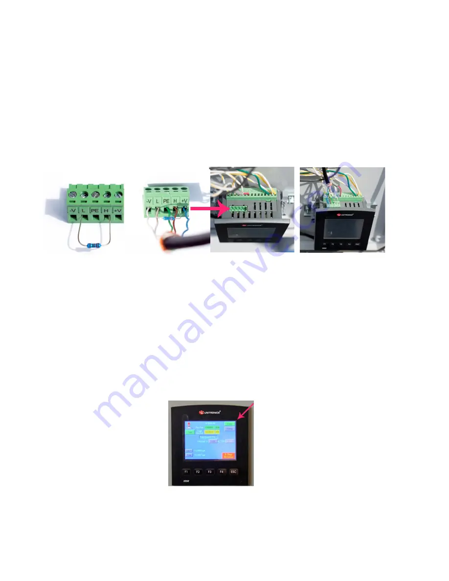
Run the CAT5 from the electrical box at the pump to the control box located in the control
house. Insert the communication wires from the CAT5 cable into the Green 5 Pin Connector and
insert it on the top of the Touch screen. You will wire both the touch screen at the pump and
the touch screen in the control house with the CAT5 cable the same way. Take care to leave
the resistor and any existing wiring in place. Unused wires from the CAT5 can be cut or taped
back.
NOTE: incorrect wire placement can burn the resistor.
+V – Blue wire
H – Brown wire
PE – Green wire
L – White wire with Brown stripe
-V – White wire with Blue Stripe
2.) Plug in or hard wire the pump power.
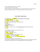
3.) Turn on the pump electrical box and the control box in the control house and look for a green
“Comm” in the upper right corner of the touch screen. If red “No Comm” is showing there is no
communications between the pump and the controller, and wiring should be checked.


