www.hi-velocity.com
© 1995-2017 Energy Saving Products Ltd.
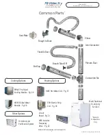
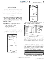
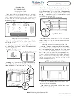
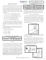
With both the Main Plenum and Rough-In Boot installed,
there is now only the connection of the two. This is done with
the 2” (51mm) or HE Flexible Branch Duct. Keep in mind that the
minimum duct length is 10 feet, with a maximum length of 25 feet
(7.62m). Branch duct runs should be kept as short as possible to
maximize the airflow through these runs. Energy Saving Products
supplies the 2” (51mm) and the HE flexible duct in three different
configurations:
•
2”
(51mm
) x 10’
(3.05m)
AFD (Assembled Flex Duct)
•
2”
(51mm
) x 15’
(4.57m)
AFD (Assembled Flex Duct)
•
2”
(51mm
) x 25’
(7.62m)
UFD (Unassembled Flex Duct)
•
HE x 10’
(3.05m)
AFD (Assembled Flex Duct)
•
HE x 15’
(4.57m)
AFD (Assembled Flex Duct)
•
HE x 25’
(7.62m)
UFD (Unassembled Flex Duct)
All configurations are available in both R4.2 and R8 R Values.
The 2” (51mm) and HE AFD come complete with the necessary
components for one complete ten foot or fifteen foot branch run.
The 25’ (7.62m) UFD is to be used only to extend these runs if
needed.
If extending branch runs longer than the minimum 10’ length,
contact the system designer, or reference Table DUC-02 for branch
duct losses on extended runs.
HE Duct is designed as a direct alternative for two 2” (51mm) flex
duct of the same length used in Hi-Velocity Systems. No changes
are required to fancoil selection and main plenum duct sizing.
HE Duct utilizes the same selecting process as the standard 2”
(51mm) flex duct, a complete and comprehensive heat loss/gain
must be completed in order to select fancoil, plenum size, and
outlet quantities.
The HE Duct is designed to directly replace
two (2) standard 2”
(51mm)
outlets, therefore when an area
requires multiple outlets, a single HE outlet can replace two of
the standard 2”
(51mm)
ducts. Any combination of 2”
(51mm)
ducting, HE ducting, and drilled outlets can be used, following
the minimum and maximum outlets as per unit selection.
HE Duct
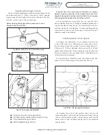
Fig. DUC-12 - Drill Hole
Branch Take-Offs (BTO)
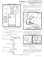
The locations for the Branch Take-Offs should be determined
before any drilling is done. Holes need to be a minimum of 18”
from any elbows or tees. Holes need to be drilled a minimum
of 6” apart on center (152mm) for 2” flex, and 7” (178mm) apart
on center for HE flex. Once all spots are marked for the Branch
Take-Offs, a hole saw is used to drill the outlets - 2 1/2” (63mm)
for 2” (51mm) Branch Take-Offs and 3 ¼” (82mm) for HE Branch
Take-Offs. (Fig. DUC-12).
Example: If a 3 Ton Unit has 24 outlets of the normal 2” X 10’
(51mm) flex duct, you can change to 12 HE X 10’ Duct outlets, or
8 HE Duct and 8 2” (51mm) Duct outlets, or any combination to
give you the equivalent. See Specification & Sizing Pgs 1,2 for
Air Flow data.
Flexible Duct
Duct Size
Max CFM Output
TWO
2” (51mm) Flex Duct
32 CFM X 2 (15 L/s X 2)
ONE
HE Duct
65 CFM (31 L/s)
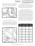
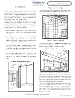
After all the holes have been drilled in the main plenum, the
Branch Take-Offs are then installed. The Branch Take- Off is
placed over the hole with the gasket in between (Fig. DUC-13a).
The curvature of Branch Take-Off is aligned so it matches the
shape of the plenum. With the opening fully over the hole push
the BTO tight against the main plenum and secure with four ¼”
(7mm) self tapping screws (Fig. DUC-13b).
It is
NOT
recommended to connect any Branch Take-Offs until
all holes have been drilled, as it may be necessary to rotate the
plenum to drill the outlets.
Fig. DUC-13a - Branch Take-Off
Fig. DUC-13b - Securing
Module DUC
Installing Plenum and Branch Duct (4/9)
Module DUC Installing Plenum and Branch Duct (4/9)
Flexible Branch Duct
2” and HE Flex Duct
Tubing Length
Adjustment Factor
10’
0%
15’
10%
20’
20%
25’
35%
Outside Diameters of Flexible Duct:
2” - R4 = 4.5” (114mm)
2” - R8 = 6.5” (165mm)
HE - R4 = 5.5” (140mm)
HE - R8 = 7.5” (191mm)
-13-
Table DUC-02 - De-rating Values


