www.hi-velocity.com
© 1995-2017 Energy Saving Products Ltd.
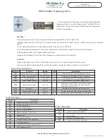
Hertz Output
Outlet Velocity
Static Pressure
Cooling Mode:
55-66 Hz
1250-1400 FPM
0.8-1.2”wc
Heating Mode:
45-66 Hz
1100-1400 FPM
0.6-1.2"wc
Constant Fan:
25-35 Hz
500-900 FPM
0.2-0.5”wc
Quick Reference Guide
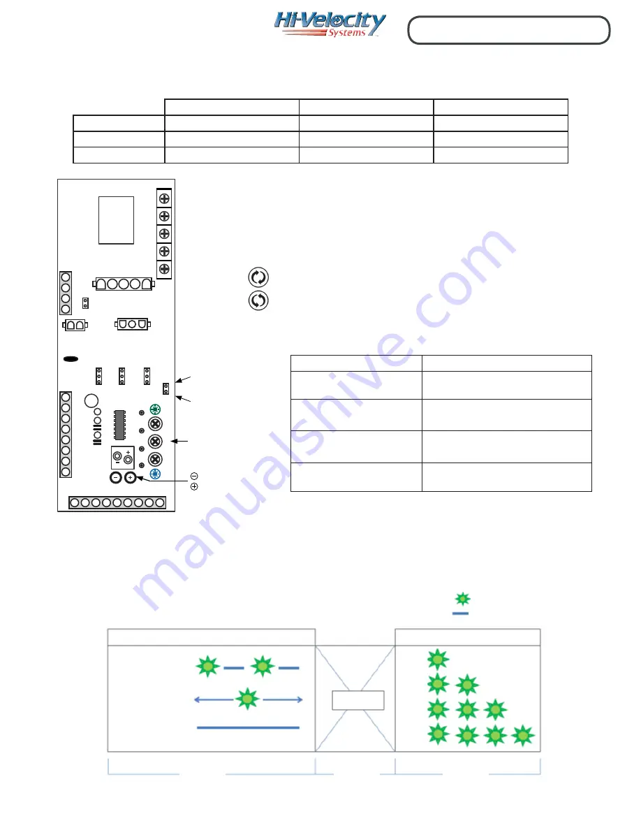
Fan Adjustment Trim Pots
Increase Airflow (Clockwise)
Decrease Airflow (Counter Clockwise)
Jumper Pin Settings
LED Description
LED 1
- Pump timer/Operation Mode Indicator Light
LED 2
- Pressure Sensor Indicator Light
Quick System Setting Reference
H1 Emergency Disconnect:
(Remove pin to activate)
H2 Timer:
Activates auxiliary relay for 5 min
every 24 hours.
H3 Mode (Auto):
Blower output speed modulates
dependent upon static pressure.
H3 Mode (Manual):
Blower output speed operates at fixed
flow rate.
H4 Delay:
Cooling/20second, heating/30 second
fan delay, and 30 second post purge.
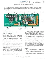
Note: If trim pots don’t modulate the blower speed,
check S/A Static Pressure pressure hose orientation
and make sure the t-stat call
is the same as the trimpot
being adjusted.
On: (Active)
On: (Inactive)
Off:
Pump Timer Status:
Fan Operation Mode:
No Light
2 Seconds
2 Seconds
2 Seconds
= Light On
= Light Off
G
W
Y
D
- Hertz will be displayed on the Variable Frequency Drive digital display.
- Outlet velocity is based on ideal noise levels.
- Static Pressure reading must be taken perpendicular to airflow, minimum
of 18” away from supply air collar of fan coil.
- Quick references should only be used to roughly set fan coil, not
to be used as primary fan coil set up method.
Notes:
-29-
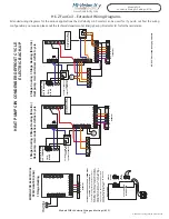
Module WIR
Hi-Velocity Wiring & Settings (9/10)
Module WIR Hi-Velocity Wiring and Settings (9/10)
Pump timer & Mode Indicator Light Sequence (Green LED1):
ON: (ACTIVE)
PUMP TIMER STATUS
ON: (INACTIVE)
OFF:
FAN OPERATION MODE
NO LIGHT
D
W
Y
G
2 SECONDS
2 SECONDS
2 SECONDS
INCREASE AIR FLOW
(CLOCKWISE)
DECREASE AIR FLOW
(COUNTER CLOCKWISE)
FAN ADJUSTMENT TRIM POTS
W1 W2 C
R Y2 Y1 D O/B
G
R
Y1
W2
W1
FZ
FZ
Y2
C
F1
AUXILIAR
Y RELA
Y
(HEA
TING)
L
L
L2
L2
N L1 L1
A3
A2
A1
L
N
COOL
HEA
T
FAN
LED
L1
J8
ON
OFF
H2
TIMER
AUTO
MAN
H3
MODE
ON
OFF
H4
DELAY
J5
J7
J4
U2
J3
R8
R7
R6
G
C
H
F
318.28 Pcbw-001sep-042
J2
N
C
Ri
Ro
H1
J9
J1
LED
L2
PSB CIRCUIT BOARD
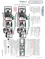
THERMOSTAT
24v OUTPUT
EMERGENCY
DISCONNECT
C
Red
+
-
Trim Pots (Cooling,
Heating & Constant Fan)
Atmospheric Pressure
S/A Static Pressure
10 VDC Black Wire (-)
10 VDC Red Wire (+)


