background image

www.hi-velocity.com

© 1995-2017 Energy Saving Products Ltd.

Check 


Transformer Plugs


Connected?

Verify 

24v power 

between 

R & C

Y

Connect 

Line 

Voltage plug

 and 

return to 

start

Check that 

Line Voltage

 wiring 

from breaker is proper

N

Line Voltage plug


connected?

Y

Y

N

N

Return to 

Start

Signal from 

Thermostat

?  (Check across 

Y1/Y2 & C or W1/W2 & C)

N

Connect 

Transformer Plugs


and 

return to start

Y

N

Set 

Thermostat 

Temperature

 and Switch


for Constant Fan, 

Heating or Cooling

N

Fan

 running?

N

Finished

Y

Fan

 running?

Y

Y

Y

Y

Check for 

Continuity

 through 

Thermostat

N

Replace 

Thermostat

N

N

Finished

Replace 

24v Transformer

Disconnect 

24v 

Transformer plug

 with two 

Red Wires from middle of 

Circuit Board and check for 

24v

 from Transformer

N

Is

 T’Stat

 set for


Constant 

Fan

Cooling


or 

Heating

?

Check 

Resettable 

Fuse

 (F1) for heat - 

Caution: Extremely 

hot if tripped

Check for broken or 

incorrect wiring between 

Thermostat 

and 

Board

Check

 24v Wiring

 for a dead short and 

for possible 

second 24v source

 being 

input into the Circuit Board i.e. Y1 or 

Y2 & C on 24v Output Terminals.

Y

Fix or replace 

Wiring

Verify 

Line Voltage 

power 

between 

L and N

-46-

Module HE-Z DIA Diagnostics & 

Trouble Shooting (5/8) 

Module DIA Diagnostics & Trouble Shooting (5/8)

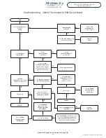
Troubleshooting - 24Volt Thermostat to PSB Circuit Board

Start

Refer to 

Trouble 

Shooting - Motor 

Not Running

Refer to 

Trouble 

Shooting - Motor 

Not Running

Summary of Contents for HE-Z Series

Page 1: ...nstallation Manual 051717 HE Z Series Installation Manual Small Duct High Velocity Heating Cooling and Home Comfort Systems Features Quiet Operation Constant Air Circulation Multi Positional Fan Coil Easy Installation Maintenance Space Saving Small Diameter Ducts Zoning Capable right out of the Box Many Attractive Vent Plate Options Superior Heating Cooling and IAQ Eliminate Hot and Cold Spots ...

Page 2: ...RPM Refrigerant Module Installation RPM E Pgs 31 35 Specifications Mounting Drain Connections Piping Brazing Evacuating Charging Heat Pumps Trouble Shooting Module WCM Chilled Water Coil Installation Pg 36 Mounting Piping Specifications Module HWC Hot Water Coil Installation Pg 37 Installation Piping Specifications Module ESH Electric Strip Coil Installation Pgs 38 39 Placement Configuration Wirin...

Page 3: ...on Parts RPM E Pre Piped Cooling Module Pg 29 Cooling Options Heating Options Other Options HWC Hot Water Coil Pg 37 WCM Chilled Water Module Pg 36 ESH Electric Strip Coil Pg 38 Hi Velocity Air Purification System Example Configuration Only Connection Tee Module INT Introduction to Hi Velocity 1 3 Module INT Introduction to Hi Velocity 1 3 WEG Variable Frequency Drive Pg 22 3 Circuit Board Pg 21 ...

Page 4: ...ructure evenly Use of a lower CFM across the cooling coil means that the Hi Velocity System can remove up to 30 more moisture from the air than conventional systems leaving a constant and comfortable temperature on the skin surface Ease of Installation The Hi Velocity System can be installed in 25 percent less time than a traditional heating system and is equally suitable for commercial and reside...

Page 5: ...its and the VFD Motor EPC Controller EPC Circuit Board and PWM Control HE Units are free from defects in workmanship for three years from date of original purchase The Electric Strip Heater is free from defects in workmanship for three years from date of original purchase Energy Saving Products Ltd is proud to offer you a limited warranty This warranty applies strictly to the first purchaser and o...

Page 6: ...ical to the operation of the Hi Velocity System for optimum home comfort The outlets should be located where it is considered to be a low traffic area Typical areas are in the corner of a room or to the side of a window or door When the vents are properly located the home owner can expect to have a nearly draft free home Fig OTL 02 Six Seven inches 152mm 178mm on center Outlet Installation PLEASE ...

Page 7: ...lace prior to installation To prevent damage during construction do not cut out the Rough In Caps until the vent plates are ready to be installed Installing Vents in Kick Spaces In kitchens and bathrooms it is sometimes hard to find a low traffic area so an alternative is to locate the vents in the kick space under the counters Our Vent plates have a 4 102mm or 5 127mm diameter which may not fit i...

Page 8: ...P 02 Counter flow 8 Module FCP Hi Velocity Fan Coil Placement 1 2 The Hi Velocity System fan coil is manufactured with a direct drive permanently lubricated VFD Motor that is mounted within the blower All Hi Velocity fan coils are single side access The blower assembly can easily be slid out by removing the three mounted bolts that attach it to the center plate In some instances the electrical box...

Page 9: ...in connections are on the bottom Fig FCP 09 and that no screws puncture the drain pan or coil The WCM and WM chilled water coils are a horizontal airflow with a vertical position of the coil while the RPM E is also a vertical coil with multiple air flow capabilities See the corresponding manual included with the coil for detailed installation instructions Fig FCP 05 Attach flanges to Unit Slide th...

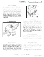
Page 10: ...ors There are five types of connections that are possible with the Hi Velocity System All of the connections are done as follows Place the joint connector cap tee or elbow inside the plenum you intend to connect Push the plenum over the fitting as tight as possible Use four screws on each side of the connector alternating the screw locations as indicated in Fig DUC 04 Fig DUC 03 Connectors 1 Tee C...

Page 11: ...g the plenum duct between joists in the basement sheet metal strapping should be used supplied by the installer not the factory to secure the plenum in place Fig DUC 09 Fig DUC 09 Use Metal Strapping When located in ceiling spaces the duct may be laid upon ceiling trusses Run the duct work low so that it can be covered with the house insulation Fig DUC 02 Insulation Sleeve Any time the duct will b...

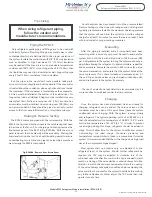
Page 12: ...duct sealant or foil duct tape In some installations it is necessary to reduce the size of the main plenum Caution must be used when reducing plenum size since smaller ducts can handle less number of outlets Also when running the plenum duct past 75 of max distance it is best to keep full size plenum duct to reduce restriction in the main plenum Keep in mind that once reduced the main plenum canno...

Page 13: ... ducts Any combination of 2 51mm ducting HE ducting and drilled outlets can be used following the minimum and maximum outlets as per unit selection HE Duct Fig DUC 12 Drill Hole Branch Take Offs BTO The locations for the Branch Take Offs should be determined before any drilling is done Holes need to be a minimum of 18 from any elbows or tees Holes need to be drilled a minimum of 6 apart on center ...

Page 14: ...oles 60mm Fig DUC 16b Add insulation at each joist When installing the flexible duct in areas in which you must run opposite to the direction of solid joists some drilling may be required It is recommended to drill the smallest hole possible Fig DUC 15 in order to maintain structural integrity Check with local code laws and ensure that it is allowable to drill holes through the joists before proce...

Page 15: ...Fig DUC 22 Ensure the vent is in the fully open position If the flexible duct is in an unconditioned space then all connections must be taped to ensure a continuous vapour seal This includes the Branch Take Off and the vent Rough In Boot Try not to damage the vapour barrier on the flexible duct If it is damaged holes must be taped If possible try to run the flexible duct between the insulation and...

Page 16: ...along the score lines of each corner Fig DUC 26 This will allow the Rough In Boot to be completely hidden with a beauty ring Fig DUC 32 Fig DUC 26 Trim off the 4 corners The Rough In Boot is then connected to flexible duct and mechanically attached with a self tapping screw Fig DUC 27 Fig DUC 27 Secure flex to Rough In Boot Next the flex is fed back into the wall and Rough In Boot slid into the ho...

Page 17: ...iple vents into linear grills the 2 51mm vents must be a minimum of 6 152 4mm on center from each other 7 178mm for HE vents Fig DUC 35 Same rules apply for vents in linear grills as a single outlet installation see Module OTL Outlet Installation for more information on vent placement Fig DUC 36 Outlet no more than 2 51mm from grill 6 7 2 The outlet of the Rough In Boot must be no more than 2 51mm...

Page 18: ...outlets larger than 2 51mm is not recommended with too large of an opening in the main plenum the static pressure may drop to an unacceptable level Fig DUC 37 6 152mm Apart on center When drilled outlets are used in a ceiling install drill the outlets at a 45 angle to properly circulate the room air Fig DUC 38 Plenum Runs on Ceiling Fig DUC 38 Airflow 45 angle to floor Fig DUC 39 6 152mm Airflow p...

Page 19: ...esigning the return air for a Hi Velocity System there are a few things to consider It is common to use centralized return air with systems that have rooms that are within a common area Separate floors or rooms that have high loads and require a large amount of supply air flow should have their own return air or be tied into the centralized return air to allow the air to return back to the fan coi...

Page 20: ...M Refrigerant Module Installation Module WCM Chilled Water Coil Installation Module HWC Hot Water Coil Installation Module ESH Electric Strip Coil Installation These manuals are included with the coils and are also available online at www hi velocity com For filter options and other Add Ons available from Energy Saving Products see Module OPT Options and Add Ons Once the return air has been cut ou...

Page 21: ...tomatically started when there s a call for heat Circulator timer chip is provided to prevent water stagnation in potable water systems and to provide pump rotor protection for water source heating and cooling Auxiliary Relay Terminals Heating VDC Control Method Switch Pressure Sensor Indicator Light Fan Adjustment Trimpots Operation Mode Indicator 0 10v DC Output Fan Delay On Off Switch T Stat Co...

Page 22: ...tection E04 acts when Heatsink Temperature reaches 103 ºC P014 Last Fault 00 to 41 EXX Indicates the Code of the last occurred Fault P015 Second Fault Occurred 00 to 41 EXX Indicates the Code of the 2nd last occurred Fault P016 Third Fault Occurred 00 to 41 EXX Indicates the Code of the 3rd last occurred Fault Features Purposely oversized to ensure increased reliability and higher efficiencies at ...

Page 23: ...IARY RELAY OPERATION SEE BELOW FOR LIGHT OPERATION SEQUENCE 6 SEE INSTALLATION MANUAL FOR MORE DETAILED WIRING DIAGRAMS 7 8 FAILURE TO SET PROPER AIR FLOW AND OR OPERATION OF THE SYSTEM MAY RESULT IN DAMAGE TO EQUIPMENT 9 FAILURE TO READ AND FOLLOW ALL INSTRUCTIONS CAREFULLY BEFORE INSTALLATION COULD CAUSE PERSONAL INJURY AND OR PROPERTY DAMAGE 10 ENSURE THAT THE FILTER IS KEPT CLEAN AT ALL TIMES ...

Page 24: ...ted the Fire Disconnect Jumper Pin Header is Present Y2 2nd stage Cooling Runs at the Cooling speed when 24v R is supplied set by the Cool trim pot Y1 1st stage Cooling Runs at the Cooling speed when 24v R is supplied set by the Cool trim pot The difference between a Y1 call and a Y2 call is the output terminal that will be energized with 24v Y1 energized on t stat terminal strip will provide 24v ...

Page 25: ...vent stagnant water on off The jumper pin header H2 will need to be in the ON position for the timer to be active H3 Mode Switches the control method used by the PSB to control motor speed Auto uses the pressure transducer in order to modulate fan speed to maintain a constant supply pressure Man allows for direct speed control of the motor by passing the pressure transducer The jumper pin header H...

Page 26: ... Y2 C A3 A2 A1 L N J5 J7 J4 O B Y2 Y1 R C W1 CONDENSER THERMOSTAT ANTI ICE CONTROL E W2 C R Y2 G Y1 2 Stage Cooling 1 Stage Heating W1 W2 C R Y2 Y1 D O B G R Y1 W2 W1 FZ FZ Y2 C A3 A2 A1 L N J5 J7 J4 O B Y2 Y1 R C W1 CONDENSER E W2 C R Y2 G O B THERMOSTAT Y1 ANTI ICE CONTROL 2 Stage Cooling 3 Stage Heating Heatpump E W2 C R Y2 G O B Y1 ANTI ICE CONTROL O B Y Y R C W1 CONDENSER E W2 C R Y G O B THE...

Page 27: ...AT G C R Y COOLING CIRCULATOR HEATING MODE OPTIONS REFER TO AUXILIARY CONTACT INFORMATION FOR W1 AND W2 W1 W2 C R Y2 Y1 D O B G R Y1 W2 W1 FZ FZ Y2 C A3 A2 A1 L N J5 J7 J4 Y C CHILLER CONTACTS Chilled water Circulator C R Y G THERMOSTAT G C R Y HEATING MODE OPTIONS REFER TO AUXILIARY CONTACT INFORMATION FOR W1 AND W2 HE Z LV Z Extended Wiring Pg 2 082615 HEAT PUMP C W CONDENSER DEFROST CYCLE BOILE...

Page 28: ...ndenser defrost cycle W1 W2 C R Y2 Y1 D O B G R Y1 W2 W1 FZ FZ Y2 C A3 A2 A1 L N J5 J7 J4 C Ri Ro H1 J9 OPTIONAL 15 23 KW UNITS THROUGH THERMOSTAT STAGING THE ELECTRIC STRIP 24V TERMINALS TWO STAGE C 1 2 1 2 O B Y2 Y1 R C W1 CONDENSER E W2 C R Y2 G O B THERMOSTAT Y1 ANTI ICE CONTROL E W2 C R Y2 G O B Y1 SET AUXILIARY TIMER TO THE OFF POSITION C W1 W2 C R Y2 Y1 D O B G R Y1 W2 W1 FZ FZ Y2 C A3 A2 A...

Page 29: ... Inactive Off Pump Timer Status Fan Operation Mode No Light 2 Seconds 2 Seconds 2 Seconds Light On Light Off G W Y D Hertz will be displayed on the Variable Frequency Drive digital display Outlet velocity is based on ideal noise levels Static Pressure reading must be taken perpendicular to airflow minimum of 18 away from supply air collar of fan coil Quick references should only be used to roughly...

Page 30: ...l flicker sporadically on and off to show that it is properly sensing pressure in the system Be sure to wait 30 seconds between adjustments to allow the PSB circuit board to reach and maintain the set point If the light on the PSB circuit board remains either off or on after 30 seconds the current set point is outside the normal operating range and must be adjusted accordingly No light indicates t...

Page 31: ... width making connections to the condenser lines quick and easy Fig RPM 01 RPM E Cooling Module Configurations When installing follow the recommendations shown in Table 01 demonstrated in Fig 01 For example a horizontal application could use A to B while highboy applications could use A to B1 Do not use a combination of A to A1 or B to B1 as this would bypass the cooling coil completely A1 is not ...

Page 32: ...e fan coil Maintain the clearances recommended by the manufacturers of the outdoor unit to ensure proper airflow The outdoor unit must be installed level in a properly supported location A liquid line filter drier is recommended to be installed Outdoor Unit Installation Make all connections to the outdoor unit with rain tight conduit and fittings Most building codes require a rain tight disconnect...

Page 33: ...ically pressures are tested to the maximum operating pressure that the system will see Allow the system to hold the nitrogen charge for at least 15 minutes to ensure there are no leaks Check with local codes for proper testing procedures After the piping is installed and all components have been brazed together a vacuum pump must be used to evacuate the system from both the low and high side to 15...

Page 34: ... the valve will increase suction pressures and decrease liquid pressures while closing the valve will decrease suction pressures and raise liquid pressures Bi Flow Receiver The Bi Flow Receiver is designed for use with heat pump systems up to 5 tons and with any typical refrigerants The receiver allows refrigerant a location to migrate to during the heating cycle minimizing head pressures During c...

Page 35: ...Ensure that the proper amount of airflow is provided to the coil Check for proper air flows and return air practices Improperly charged systems run the risk of short cycling as well An undercharged system will react much the same as a system with low airflow If the charge is low enough it may trip out on low pressure If a system is overcharged it may trip out on high head pressure Ensure that the ...

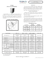
Page 36: ...e WCM Chilled Water Coil WCM WM 1 1 36 WCM WM pipe sizing Zone BTUH Pipe Size up to 40 feet Pipe Size 40 100 feet 0 35 000 0 10 3 kW 3 4 19mm 3 4 19mm 35 001 70 000 10 4 20 5 kW 3 4 19mm 1 25mm 70 001 140 000 20 6 41 kW 1 25mm 11 4 32mm Specifications WCM 50 WCM 70 1050 WCM 100 1050 WM 1750 Matching Fan Coil HE Z HE B HE 50 51 HV 50 51 52 LV 50 HE Z HE B HE HV 70 71 LV 70 LV Z LV E 1050 HE Z HE B ...

Page 37: ...k valves are required to be installed on the supply and return to prevent gravity flow from the hot water source on a call for cooling or constant fan Size your supply and return lines according to Table HWC 01 Figs HWC 02 and 03 illustrated typical pipe runs from a dual purpose hot water tank to a fan coil These drawings are only for reference as all piping has to be run according to local codes ...

Page 38: ... any shipping damage check the heating elements for any loose connections and check all porcelain insulators for any breaks Report any damage to the manufacturer DO NOT INSTALL DAMAGED HEATER Module ESH Electrical Strip Heater Installation 1 2 Module ESH Electrical Strip Heater Installation 1 2 PLEASE NOTE THE ESH MUST BE WIRED TO A DEDICATED BREAKER SEPARATE FROM THE FAN COIL Install the ESH in t...

Page 39: ...rt up all electric connections to contactors should be re checked and tightened Before each heating season the following steps are recommended Check all fuses Check resistance to ground for each circuit Check resistance phase to phase for each circuit Check the tightness of connections at all contactors and heating elements Check all contactors Check electrical connections to heating elements magn...

Page 40: ...mpact size 2 6 x 4 7 7x 12cm and light weight 3oz 85g Measures wind speed from 0 99 9 mph Available from Energy Saving Products or directly from Davis Instruments Turbo Meter from Davis Instruments Fig OPT 02 Filter Rack and Filter Available from Energy Saving Products is a 3 76mm Filter Rack Filters are 1 25mm thick Merv 3 and the filter medium is approximately 14 efficient Any after market filte...

Page 41: ...er 18 When a bypass type humidifier is used the humidifier can be mounted on the return air duct and then a 2 51mm take off from the hot air side is run back Fig OPT 05 DO NOT use any size larger than 2 51mm and be sure to install a summer shut off or it will create problems with the airflow Fresh Air Make Up Fire Stopping Humidity Control Third Party Options Fig OPT 03 Fresh Air Make up Exterior ...

Page 42: ... program for ext fault is open Wiring at DI1 to DI4 inputs is open not connected to GND E08 CPU Error Electrical noise E09 Program Memory Error Checksum Contact WEG Servicing Memory with corrupted values E24 Programming error It is automatically reset when the incompatible parameters are changed Incompatible parameters were programmed E31 Keypad HMI Connection Fault Contact WEG Servicing Inverter ...

Page 43: ...posite end of cable Fig 006 Decrease PSB trimpot of jumpered tstat setting 1 2 turn Counter Clockwise Wait 30 seconds for drive to adjust Fig 007 Adjust trimpot 1 2 turn Counter Clockwise wait 30 seconds VDC changed Return to Step 4 Replace Transformer Turn off Supply Power connect Transformer turn on Power Return to Step 5 Call Technical Support Toll Free 1 888 652 2219 Install Jumper and return ...

Page 44: ...to Step 7 9 8 7 6 5 Verify that Main Supply Voltage is present on the PSB circuit board between the L and N terminals Fig 004 4 Power Fan Coil 3 N N N Y Y Y N Y N N Y Unplug Motor Leads and test resistance ohms between Windings Figs 002 003 Jumper desired Tstat setting with R on the PSB Circuit Board Fig 001 Verify that Pressure Sensing section of PSB is functioning properly by measuring Voltage O...

Page 45: ...irflow is running at desired speed See System Commissioning and Set Up Y N Call Technical Support Toll Free 1 888 652 2219 14 X Voltage Present Fig 006 Fig 004 Fig 005 Troubleshooting Motor Not Running Fig 007 Fig 008 45 Module HE Z DIA Diagnostics Trouble Shooting 4 8 Module DIA Diagnostics Trouble Shooting 4 8 Input Voltage and T Stat section on PSB is functioning correctly VDC 9VDC PSB Circuit ...

Page 46: ... Replace 24v Transformer Disconnect 24v Transformer plug with two Red Wires from middle of Circuit Board and check for 24v from Transformer N Is T Stat set for Constant Fan Cooling or Heating Check Resettable Fuse F1 for heat Caution Extremely hot if tripped Check for broken or incorrect wiring between Thermostat and Board Check 24v Wiring for a dead short and for possible second 24v source being ...

Page 47: ...ify 24v Power between W1 W2 C Y Verify 24v Power between W2 C on 24v OutputTerminals Auxiliary Relay Activated Y1 C Y2 C W1 C W2 C Y1 for Multi Staging units only Y1 controls Blower Only if Single Stage Cooling use Y2 Verify 24v Power between X1 C Verify 24v Power between Y2 C on 24v Output Terminals Fan Running Check Thermostat Refer to Troubleshooting Motor Not Running W1 for Multi Staging units...

Page 48: ...at the Fan Coil Y N Allow System to settle and Freeze Stat to open Y N Check for open Safety Controls on Outdoor Unit Ensure System is properly Charged and Airflow is correct Refer to Troubleshooting 24v N Y Ensure System is Properly Charged and Airflow is correct N Y N Check for improper Wiring or Damage between Indoor and Outdoor Units Replace Wiring Y Replace Freeze Stat Y 48 Module HE Z DIA Di...

Page 49: ... TX and Charge good Refer to Charging on page 33 Confirm the Line Sizes are correct Confirm that the Unit is Properly Sized Confirm that all Piping is done properly Check that the TX Valve Bulb is installed correctly Is Freeze Stat working properly Replace Freeze Stat Confirm that other Safety Controls are working properly Refer to Troubleshooting 24v N N Y Y Y N N Troubleshooting Short Cycling 49...

Page 50: ...4 0 kW 27 000 7 9 kW 19 200 5 6 kW 42 100 12 3 kW 30 300 8 9 kW Max BTUH 46 F E W T kW 7 8 C 20 900 6 1 kW 14 200 4 2 kW 29 400 8 6 kW 20 000 5 9 kW 45 800 13 4 kW 32 100 9 4 kW Max BTUH 44 F E W T kW 6 7 C 22 600 6 6 kW 14 900 4 4 kW 31 800 9 3 kW 21 000 6 2 kW 49 500 14 5 kW 33 700 9 9 kW Max BTUH 42 F E W T kW 5 6 C 24 200 7 1 kW 15 700 4 6 kW 34 000 10 0 kW 21 800 6 4 kW 53 200 15 6 kW 35 100 ...

Page 51: ...4 19mm WCM 100 Fits HE Z HE B HE HV 100 101 LV 120 140 LV Z LV E 1050 25 3 8 645mm 10 1 8 257mm 18 1 2 470mm 3 4 19mm 3 4 19mm WM 1750 Fits LV Z LV E 1750 26 1 4 667mm 8 1 4 209mm 22 5 8 575mm 1 25mm 1 25mm Hi Velocity Air Purification System E F G HE PS w Merv 13 Filt Fits All 50 51 70 71 100 101 120 140 1050 Units 25 635mm 10 254mm 17 457mm HE PS 1750 w Merv 13 Fits LV Z LV E 1750 25 635mm 10 25...

Page 52: ... complete with an in house test lab Energy Saving Products prides itself on Customer Service and provides design services and contractor support For all of your Heating Cooling and Indoor Air Quality needs the Hi Velocity System is the right choice for you Phone 780 453 2093 Fax 780 453 1932 Toll Free 1 888 652 2219 www hi velocity com Hi Velocity HE Z Fan Coils Green Technology Build Smart Breath...

Reviews: