background image

Maintenance and Service

8.5.5

3. Drain the oil tank through the drain plug.

Make sure the system contains as little as
possible.

Use a container with sufficient capacity.

! NOTE

Ensure the waste oil is disposed of safely and
inaccordance with local environmental regula-
tions.

4. Change at the same time:

- all filters

5. Refit the drain plug.

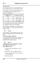
Filling the oil tank with hydraulic oil

The oil used for filling must be clean. Do not mix
different oils.

Hydraulic oil that is approved for HIAB products
must comply with one of the following standards
or equivalents:

-DIN 51524 part 3

-SS 15 54 34

-ISO 11158 HV

Suppliers of hydraulic oil must verify that the
quality and performance of the oil complies with
the above standards.

When changing from mineral oil to a non-
polluting synthetic oil, or when changing to
biodegradadle oil, contact a HIAB service work-
shop.

Operator's Manual GB

99

Summary of Contents for 422-477 HiPro CD

Page 1: ...Operator s Manual GB HIAB 422 477 HiPro CD This operator s manual is an Original Instruction and applies for cranes from serial number 4221404 4770803 2015 06 ...

Page 2: ...ly and with full satisfaction Please read the complete manual It provides detailed information about the crane safety system and the practical management and maintenance of the crane We advise you to read it carefully and familiarize yourself with your crane before you start to use it Help us to improve this manual Please send your comments and suggestions to documentation hiab com 2 Operator s Ma...

Page 3: ... 422 477 HiPro 16 3 Safety precautions and warnings 17 3 1 Operating conditions 17 3 2 Definition of a HIAB loader crane 18 3 2 1 Noise declaration 19 3 2 2 Warning signs 20 3 2 3 Maximum load 20 3 2 4 Maximum load moment 23 3 3 Signals when using a crane 26 3 4 Wind speeds 30 3 5 Use of the crane 31 3 6 Use of lifting equipment 38 3 7 Use of dismountable cranes 38 4 The Safety system 40 4 1 Safet...

Page 4: ... 76 6 3 Manual extensions option 76 7 Ending crane operation 79 7 1 Operate the crane to parking position 79 7 2 Placing the stabiliser extensions and legs in transport position 80 7 3 Switching off the safety system 82 7 4 Emergency operation Valve V91 83 7 5 TWI Transport warning interface option 84 8 Maintenance and Service 86 8 1 Service 86 8 2 Warranty 87 8 3 Follow the maintenance instructio...

Page 5: ...cartridge in the pressure reduction filter 97 8 5 4 Checking the oil tank level 98 8 5 5 Changing the hydraulic oil 98 8 5 6 Bleeding air from the hydraulic system 101 8 6 Troubleshooting 102 8 6 1 Main fuses 102 8 6 2 Faults in the HiPro crane 102 9 Decommissioning 106 9 1 Decommissioning a crane 106 10 Technical Data 108 10 1 Documentation 108 Operator s Manual GB 5 ...

Page 6: ... Operator s Manual for your crane carefully it could lead to fatal accidents or serious damage Therefore you should Study the entire Operator s Manual carefully Study the operating manuals for other add on equipment if fitted Use the crane only after having done so Follow the directions for use operation and maintenance of the crane and add on equip ment exactly Store the Technical Data and manual...

Page 7: ...NG Danger of injury to yourself or to bystanders or danger of serious damage to the crane or other objects Follow the instructions carefully CAUTION Hazard for the crane or crane components Follow the instructions carefully Important If actions are numbered 1 Do this 2 Do that 3 4 5 you should carry them out in numerical order NOTE Extra information that can prevent problems TIP Tip to make the wo...

Page 8: ...eive instruc tion from an experienced person from your own company Only then should you operate your crane Ensure that you comply with the statutory requirements of the country in which you use the crane for example certificate obligatory safety helmet DANGER Carry out yourself only the service and maintenance work you have the requisite knowledge and experience of All other maintenance work may o...

Page 9: ...controller in water or other liquid This will make the controller unusable If your crane is equipped with add on lifting equipment hoist rotator etc The operation of the crane with add on lifting equipment can differ from the oper ation as described in this manual You should therefore study the Operating Manual for the add on equipment careful ly before you use the crane Take particular note when ...

Page 10: ...system Stabiliser system Operating system 2 2 Crane base with column and slewing system The crane base column and the slewing sys tem consist of the following components Crane base with stabiliser beam column bearings and three point bridge Column this fitted to the crane base and turns in an upper and a lower bearing Slewing system 10 Operator s Manual GB ...

Page 11: ...xtensions The length of the hydraulic extension depends on the type of crane Manual extensions option These are slid by hand into the hydraulic extension JIB option Add on lifting accessories option Add on lifting accessories are placed between the boom tip and the load e g brick grapple rotator or on the crane hoist Operator s Manual GB 11 ...

Page 12: ...Structure and parts of the HIAB crane 2 3 Separate lifting accessories option Separate lifting accessories help to make or use a slinging device eye hooks shackles eye bolts etc 12 Operator s Manual GB ...

Page 13: ...cranes Stabiliser beam The stabiliser beam is a part of the crane base Stabiliser extensions The stabiliser exten sions are hydraulically slid out from the stabiliser beam Stabiliser legs Place the stabiliser legs on firm levelled ground to support the crane Stabiliser locking device Support plates The support plates are used under the stabiliser legs for additional sup port Operator s Manual GB 1...

Page 14: ...educers return filter pressure filter option 2 6 LHV Load holding valves All cylinders are equipped with load holding valves as a safety device After a crane move ment they hold the crane in position also in the unlikely event of a burst hose If there is a leak or a component fractures such as a pipe hose or a coupling the load holding valves will stop the booms from collapsing down even when the ...

Page 15: ...ersions from HIAB 422 477E 4 reach 11 7 metres to HIAB 422 477E 8 reach 20 8 metres HIAB 422 477EP 2 reach 8 4 metres to the HIAB 422 477EP 5 reach 15 4 metres The main control valve V91 CombiDrive2 and the SPACE 5000 safety system are standard equipment on the HIAB 422 477 HiPro CD The crane type and the manufacturer are marked on the serial number plate NOTE The exact technical information for y...

Page 16: ...B 422 477 E 7 JIB75X 3 4 TC1 422 477 E 5 6 JIB100X 4 5 TC1 TC2 422 477 EP 2 3 4 5 TC2 422 477 E 4 5 6 TC2 TC2L 422 477 E 7 8 TC2L Not compatible with manual extensions in version E 8 422 477 E 7 JIB75X 3 4 TC2L 422 477 E 5 6 JIB100X 4 5 TC2L Snatch block for TC2 and Available in all combinations except with manual exten TC2L sions in the versions 422 477 E 6 7 8 JIBS available in combinations 75X ...

Page 17: ...rox 29 7 mph the crane will behave unpredictably Never use the crane during a thunderstorm Never use the crane at temperatures below 40 C 40 F as the steel s properties deteriorate below this temperature WARNING At temperatures below 0 C 32 F Do not touch the operating levers during the first few minutes When starting in cold weather the wear on the hydraulic system is greater than at normal worki...

Page 18: ...the ground vehicle to a higher place Installation work beams concrete plates windows in building constructions Lifting construction material wall boards bricks blocks on a pallet fork to a build ing taking the material from the vehicle on which the crane is mounted from another vehicle or from the ground Hoisting e g beams concrete plates and any other material and equipment used in building const...

Page 19: ...he crane is specifically prepared for this Push pull with the boom system against any type of obstacle wall ground Using the JIB upside down HiPro cranes except JIBs prepared for that See Operator s Manual for your JIB 3 2 1 Noise declaration The following values for emitted noise may be taken as general and conservative values for ordinary installations of loader cranes on normal diesel engine po...

Page 20: ...ighted sound pressure level at loader crane control stations in accordance with ISO 11201 LpA 95 dB Uncertainty KpA 4 dB Particular installations can be quieter in which case a post installation noise measurement in accordance with clause 6 3 of EN 12999 2011 may be used to prove this 3 2 2 Warning signs 3 2 3 Maximum load Lifting capacity 20 Operator s Manual GB ...

Page 21: ...agram on your crane show the maximum loads you may lift in the operating reach of your crane DANGER Overloading could result in damage to the crane or in the worst case personal injury or death Never increase a hanging load since that may cause a load holding valve to open and or the vehicle to turn over Never use the crane with the OLP system switched off NOTE The extra weight of the lifting acce...

Page 22: ... load plate DANGER Never exceed the maximum weight on the load plate Load diagram The load diagrams are placed on the column and show the maximum loads your crane JIB if fitted hoist if fitted may lift in the entire working zone manual extensions excluded The load diagram drawing will also be found in the enclosed Technical Data The white area is the working zone of the crane The load curves show ...

Page 23: ...s when the first boom is fully lifted as this could cause damage to the first boom cylinder 3 2 4 Maximum load moment If your crane has reached the maximum load moment lifting capacity the OLP gives a warning and locks any crane movement that will increase the load moment This is known as an OLP situation If the second boom is raised then the following movements are locked first boom down up secon...

Page 24: ...en the legs of the sling must not exceed 120 The maximum working load usually known as the working load limit WLL in standards of a multilegged sling for general purposes is calculated by multiplying the WLL of a single leg by a mode factor in accordance with the table Max angle to Mode factor Mode factor the vertical of two legged three and four any sling leg sling legged sling degrees 0 45 1 4 2...

Page 25: ...ngle to about 10 to 30 above the horizontal plane Heavy loads Lift heavy loads with the second boom in the optimum position in relation to the first boom For this see the load plate on your crane DANGER Never exceed the maximum permissible load ing of the hook Heavy loads cannot be handled with the boom straight Set the second boom so there is an angle in relation to the first boom Loads at the ex...

Page 26: ...he load and the entire working area clearly the crane oper ator is obliged to follow the instructions and signals given by a qualified person qualified The country specific regulations for crane operator signals are to be used Signals in this manual give a number of standard signals that can be used Lift Raised arm and index finger raised Circular motion with hand Lower Arm pointing downwards and ...

Page 27: ...s and the arms to an oblique angle Very short movement Place the hands a very short distance apart with the palms facing each other The hands may be held either horizontally or vertically The next movement may be Lift lower move the lifting gear change the reach or turn Change the reach Signal with your hands Sideways movement outwards with both hands Thumbs outwards Sideways movement inwards with...

Page 28: ...s 3 3 Turn in the direction indicated Indicate the direction with the hands Open the grapple Extend the arms at shoulder height with the palms facing downwards Close the grapple Move both hands close together 28 Operator s Manual GB ...

Page 29: ...grapple a little Extend both arms at shoulder height with the palms facing upwards Make vertical movements with both arms outstretched Keep the grapple in position briefly Raise the hand drooping slightly with the fist clenched Operator s Manual GB 29 ...

Page 30: ...ground Fairly strong wind Small leaved branches make swaying 5 8 0 10 7 movements crested waves form on lakes and canals Strong wind Large branches move you can hear the wind whistling in telephone wires 6 10 8 13 8 umbrellas can only be held with diffi culty Severe wind Entire trees move the wind causes 7 13 9 17 1 difficulty when you walk into it 8 17 2 20 7 Stormy wind Twigs break off walking i...

Page 31: ...ned Look out for sewers cellars excavations etc The stabiliser legs must not be able to sink in Use support plates that are large and firm enough for your crane The plates must not bend under load Check that the support plate as it comes under load is not pushed into the ground Ensure you can see the stabiliser legs and stabiliser extensions when you are operat ing them Do not lower the stabiliser...

Page 32: ...s a load WARNING Use low force when placing the stabiliser legs on the ground Do not raise the vehicle with the stabiliser legs if the crane is equiped with only two stabiliser legs If you raise the vehicle with the stabiliser legs this may damage the stabiliser legs Check that the add on lifting accessories and separate lifting accessories are in good order Add on lifting accessories are sometime...

Page 33: ... system when operating the crane out of parking position Preparations for use DANGER Ensure that there are no unauthorised persons within the operating range of your crane TIP Mark out the working range e g with cones Put on your vehicle s warning lights Operator s Manual GB 33 ...

Page 34: ...lated insulated con conductor ductor 500 V 0 5 m 2 m 500 40000 V 1 5 m 4 m 40000 V 2 0 m 6 m Voltages are found up to 500 V to buildings 500 40000 V trams trains over 40000V power transmisson Crane operation DANGER Your crane has a safety system The safety system will help you to work safely Nevertheless you remain responsible for safe use of the crane Therefore always work according to the oper a...

Page 35: ...f signals Make certain that you and the person assisting you know these signals Pay attention to the safety of the person giving the signals Never move the vehicle if you have a freely suspended load on the crane Never walk or stand under a suspended load During operation never stand below the boom system or load Do not slew the crane nor lift the first boom nor lift the second boom into their end...

Page 36: ...tricted spaces for example windows Check that the boom system can move up and down freely The boom system will bend somewhat when loading and unloading the crane If the boom system is in a high position first boom above 70 do not allow the boom to lower at full speed The crane could go into an uncontrolled movement Be careful if in particular the OLP gives an early warning When loading the vehicle...

Page 37: ...els etc Pay attention to overhead power lines Make sure that no part of the crane ever comes in contact with overhead power lines For further instructions see vehicle s manual s Ending crane operation DANGER Always end crane operation as follows After use always place the crane in the transport position Withdraw the stabiliser legs and stabiliser extensions Check that the locking mechanisms are pr...

Page 38: ...just lifting accessories when you are working on the crane After the lifting accessories have been fitted 1 Check that the lifting accessories are securely fixed 2 Only after this should you use your crane WARNING Clean the couplings when connecting and disconnecting lifting accessories Dirt can damage the hydraulic system Take care that your fingers are not trapped 3 7 Use of dismountable cranes ...

Page 39: ...Safety precautions and warnings 3 7 WARNING Take care when mounting dismounting the crane on off the vehicle Roughly handling can seriously damage the crane or the vehicle Operator s Manual GB 39 ...

Page 40: ... system HiPro CD V91 SPACE 5000 NOTE The safety system provides a large number of functions Certain functions are standard others are options If you do not use the system for 30 minutes it will switch itself off in order to prevent draining the truck battery This feature can be cancelled Contact your HIAB service workshop 4 2 How the safety system works The safety system works as follows On the cr...

Page 41: ... when a spool is moved too much power to the dump valve is cut all movements are stopped Fault monitoring When there is a fault in the safety system it will give an immediate warning Depending upon the fault the crane speed and or the load capacity will be reduced When the fault is serious use of the crane is blocked completely DANGER Never try to repair the safety system yourself Repairs may only...

Page 42: ...d oil Dump valve 1 To prevent high pressure and thereby unnec essary heating of the oil there is an automatic dumping function When no lever movement has been made for 3 seconds SPACE system opens the dump valve and the oil is returned directly to the hydraulic tank As soon as the operator moves a lever the valve closes Dump valve 2 Allows operation of the stabiliser extensions and legs only when ...

Page 43: ... control valve user panel SPACE 5000 remote control CombiDrive2 with radio with cable connected 4 5 Main control valve The speed of a function corresponds to the extent of the lever movement regardless of the load and other functions as long as the oil flow is sufficient When the oil flow is insufficient one or more functions might reduce their speed When remote control is used the oil flow is all...

Page 44: ...The Safety system 4 5 Main control valve lever function Remote control lever function 44 Operator s Manual GB ...

Page 45: ...lve The stabiliser control valve is equipped with 2 levers on each side of the crane The levers have the functions Stabiliser leg upward downward Stabiliser extension out in The stop button affects the oil supply to this valve Operator s Manual GB 45 ...

Page 46: ...ply to this valve The stabiliser control valve can be operated manually or remote 4 8 OPS Operator Protection System option OPS is a system that protects the operator from the boom system s movements when operating the crane The OPS system is integrated in the SPACE system and it uses a sensor on the rack and tilt indicators on the boom system to indicate the position of the crane It creates a vir...

Page 47: ...opped immediately ON OFF button with the symbol to switch the safety system On Off Button with the symbol To switch on the remote control and radio control Button with the symbol To select manual function Confirm view button with the symbol To confirm full view of operating the stabilis er extensions outward 4 9 1 Indicator lights on user panel SPACE 5000 Power On Green light on The system is on G...

Page 48: ...y ADC mode Hoist LED Green light on Hoist mode Red light flashing 90 of OLP pressure Red light on 100 of OLP pressure Cylinder pressure Green light A on 50 of OLP pressure LED s Green light A B on 70 of OLP pressure Red light A C flashes 90 of OLP pressure Red light A D on 100 of OLP pressure Red light blinking from A D OLP release Remote control Green light on Remote control Good radio connec tio...

Page 49: ...ovides information about which menu has been chosen as well as indicat ing the radio reception conditions battery status fault information micro ADC manual extension and so on The side displays show the symbol for the function which each lever activates in the chosen menu When the operator changes menu the symbols change to the functions that become active Via cable A four metre cable is supplied ...

Page 50: ...ed Alternating symbols will not be updated at tem peratures below freezing In order to prevent accidental menu shifts in cold weather below 10 C there will be a time delay before any menu button will react to a second depression In order to avoid this inconvenience HIAB recommends that whenever the controller is not in use it should be stored in a compart ment where the temperature exceeds 10 C Ce...

Page 51: ...e Indicates that the LSS V function is active shown enlarged for three seconds and then return to normal size MEWP Mobile Elevating Work Plat HDC form Indicates that the HDC function is active Indicates that MEWP if present is active Signal strength JDC The bars show the radio signal strength Indicates that the JDC function is active Five bars indicate optimum reception condi tions If the symbol f...

Page 52: ...Symbol appears enlarged in the center of the display After three seconds it returns to normal size and moves to the upper part of the display Critical error Symbol remains enlarged in the center of the display The crane stops Error code display The control system has the possibility to send error codes to the controller By pressing button on the left hand side below the display handle The centre d...

Page 53: ... Button CRANE menu Button EXTRA menu button ON OFF menu In each of the main menus the operator can step through submenus by pressing the same button repeatedly e g 1 2 3 and then back to 1 again The restriction is that one function is only present on a specific lever If a lever is faulty or deflected at startup the lever is disabled The other levers operate in the usual way With the 2 extra levers...

Page 54: ...y lever there is a correspond ing function which it controls This appears in the left or right display When the menu changes by pressing the button for CRANE menu the symbols change and the functions are activated in the current menu The symbols are stored in a symbol library and can be configured set via the terminal program for a CE crane Symbols for the 8 lever controller Centre Left side displ...

Page 55: ...1 2 3 The Safety system 4 11 Symbols for the 6 lever controller Left side display Centre Right side display display CRANE MENU Operator s Manual GB 55 ...

Page 56: ...ion to the lever The symbols are configured in the same way as for the CRANE menu The same method is used for stepping between the sub menus Left is defined as the side of the crane where the main control valve is normally placed The order of the levers is customized For the 6 lever controller If the crane has 1 stabiliser control valve the order of the levers should be Functions lever forward on ...

Page 57: ...leg down Menu 3 Lever Functions lever forward on the con troller 2 Right crane stabiliser extension out 3 Right crane stabiliser leg down 4 Right auxiliary stabiliser extension out 5 Right auxiliary stabiliser leg down For the 8 lever controller If the crane has 1 stabiliser control valve the order of the levers should be Lever Functions lever forward on the con troller 3 Left stabiliser extension...

Page 58: ... con troller 1 Left auxiliary stabiliser extension down 2 Left auxiliary stabiliser leg out 3 Left crane stabiliser extension down 4 Left crane stabiliser leg out 5 Right crane stabiliser extension out 6 Right crane stabiliser leg down 7 Right auxiliary stabiliser extension out 8 Right auxiliary stabiliser leg down 58 Operator s Manual GB ...

Page 59: ... entered directly into the window that corresponds to each function Only ordinary numerals and the letters of the English alphabet can be used For each sub menu four functions may be defined The functions are controlled by levers 2 5 A lever may be deflected in any direction in order to activate the corresponding function ON OFF MENU Left side display Centre display Right side display FRONT REAR P...

Page 60: ... battery is approximately 3 hours The battery charger is designed not to damage the battery even during long continuous charging Operating ambient temp Battery 0 to 45 C A charged battery The voltage level of a fully charged battery is approximately 8 4V and it provides about 5 8 hours working time Note that the battery voltage remains between 7 6V and 7 5V for a long time Therefore the battery vo...

Page 61: ...er and operating the crane Locking the controller 1 Press and hold button and while the stop button is pressed 2 Keep button and pressed while pulling out the stop button The centre display then shows a large locked padlock symbol Unlocking the controller 1 Press and hold button and while the stop button is pressed 2 Keep button and pressed while pulling out the stop button 3 Release button and Th...

Page 62: ... Automatic Speed Control The ASC function automatically provides the extra power by reducing the speed smoothly when working close to the rated capacity When the load decreases normal speed is restored ADC Automatic Duty Control The purpose of the ADC function is to increase the lifting capacity by 10 The first boom pressure sensors indicate if there is a positive or negative pressure on the first...

Page 63: ... smooth simultaneous operation is achieved Controlling crane speed Use the button to change resolution of the lever to 50 or 20 of normal speed Slewing sector option Within slewing sector lifting capacity can be reduced due to stability The overload warning will be given at a lower load in the limited sector than outside the sector In case of an overload warning you may slew out of the sector but ...

Page 64: ... the bubble is between the two circles the crane inclination is between 0 and 5 If the slope exceeds the permitted inclination unintentional crane movements can occur Particular case Working with boom sys tem beyond 60 To avoid side deflection and in order to guarantee the safest operation when working with e g hoist and or JIB MEWP applica tions the vehicle has to be completely lev elled in any d...

Page 65: ...o low during crane operation the vehicle s engine could stall The maximum rpm may depend upon a governor on your PTO combination CD2 Start the safety system The operating levers must be in neutral position before start up To activate the system press the On Off button on the user panel The LED above the button starts to blink The system will check itself 2 4 seconds Operator s Manual GB 65 ...

Page 66: ...hts 3 To activate the controller pull out the stop button by turning it clockwise The radio starts to establish a link with the decoder Wait is displayed while radio contact is being established Decoder LED s colour green yellow red The decoder is powered on when remote control is chosen LED is lit The LED on the decoder starts to blink Radio link established When the radio link has been establish...

Page 67: ... in CRANE 1 menu regardless of which menu was active when the controller was stopped CD2 Operating the stabiliser system WARNING All levers must be in neutral position DANGER When you are operating the stabiliser exten sions Make sure that you have full view of the stabiliser extensions Do not stand in front of hydraulically operated stabiliser extensions From remote controller Turn the stop butto...

Page 68: ...ser extensions and legs must be fully extended and set to the ground without lifting the wheels off the ground NOTE The stabiliser leg downward movement is auto matically stopped when pressure to the ground is sufficient To operate the stabiliser legs further downward move the lever once again For cranes with VSL the stabiliser leg downward movement is automatically stopped at a pre given force le...

Page 69: ...he maxi mum ground pressure is less than 4MPa Operation with non tiltable stabiliser legs 1 Unlock the catcher 2 Extend the stabiliser extension 3 Position the loose leg support plate onto the ground if delivered 4 Set the stabiliser leg to the ground Repeat for the stabiliser extension and leg on the other side of the vehicle When there is an additional set of stabiliser legs option Repeat the pr...

Page 70: ...r until the stabiliser leg has turned 180º 4 Turn the lever 180º and check that the locking pin is automatically locked 5 Extend the stabiliser extension 6 Position the loose support plate onto the ground if delivered 7 Set the stabiliser leg to the ground WARNING Always check that the stabiliser legs and the stabiliser extensions are in correct position and tilting mechanism is locked in working ...

Page 71: ...ating instruc tions for add on equipment carefully Once the stabiliser extensions and legs are ready you can start using the crane 1 If stabiliser system is under manual control push button on the user panel 2 If using remote control push button on the controller to change the menu into crane operation DANGER Always operate manually controlled crane from the position indicated Operator s Manual GB...

Page 72: ...iliser extension is extended the catch release automatically the stop in the first boom 3 Raise the boom system 4 Extend the hydraulic extensions 5 Slew the crane to the working position The crane is now ready for use NOTE As soon as you have selected remote control operation it is impossible to operate the main control valve levers 72 Operator s Manual GB ...

Page 73: ... The yellow lamp on the lamp pole option flashes and the cylinder pressure LED s flash red When 100 of the maximum permitted pressure is reached the OLP cuts in The display shows whether a particular motion is prohibited or if the crane is subject to OLP The red and the amber lamps on the lamp pole option will light all the time and the cylinder pressure LED s will light continuously Operator s Ma...

Page 74: ...ll motions that would increase torque are blocked If the operator attempts to activate a blocked function the function symbol is replaced by a cross while the lever is deflected When the lever is returned to the neutral position the cross disappears and the information returns Operate permitted load reducing functions only NOTE Do not operate heavy loads with the extensions fully retracted In an O...

Page 75: ...is period it is possible to operate an appropriate crane function so as to correct the overload situation Only one unallowed function at a time can be operated Extension out cannot be operated The unlocked padlock will appear in the centre display On the user panel the cylinder pressure LEDs and the LED for padlock symbol will flash red Manual control If one prohibited movement is used all move me...

Page 76: ...om and extensions movements DANGER Only use the BDA override to get the crane out of a locked position Operating the crane out of parked position When the angle ß is 135º between the horizontal and second boom second boom and extensions can move without any restrictions 6 3 Manual extensions option Operation with manual extensions Always extend the hydraulic extensions first then the manual extens...

Page 77: ...hat can be handled Do not lift loads heavier than the values stated on the hook attachment To lift heavier loads than specified on the sign the hook position must be moved to the nearest hydraulic extension in accordance with the load plate on the crane To retract the manual extensions 1 Locate the boom system as close as possible to the horizontal position but low enough to reach the extension by...

Page 78: ...e button and Horn button until symbol on the centre display is lit The lamp for manual extension is lit on the user panel The manual extensions are now included in the OLP protection The lifting capacity will be reduced automatically De activate Push the button and again The symbol on the centre display goes out The lamp for manual extension goes out on the user panel 78 Operator s Manual GB ...

Page 79: ...from the position indicated in the figure NOTE If the crane has OPS press the button and hold it in while carrying out points 3 5 1 Slew the crane until the crane is square on the vehicle 2 Retract the extensions completely 3 Raise the first boom 4 Operate the second boom against the under side of the first boom 5 Lower the first boom completely checking that the catch is completely into the slot ...

Page 80: ...sure that the stabiliser legs and the stabiliser extensions are in transport position and securely locked WARNING Do not put your foot on the support plate Operation with non tiltable stabiliser legs 1 If loose support plate delivered rectract a little the stabiliser leg if not go to step 3 2 Unlock the loose support plate 3 Retract the stabiliser leg 4 Retract the stabiliser extension completely ...

Page 81: ...l lock the stabiliser exten sion Repeat for the stabiliser extension and leg on the other side of the vehicle When there is an additional set of stabiliser legs option Repeat the process for the 3rd and 4th stabiliser legs Operator s Manual GB 81 ...

Page 82: ...rotate automatically to vertical position 6 Turn the lever 180º and check that the locking pin is in and the lever cannot rotate 7 Retract the stabiliser extension completely WARNING Risk of crushing injuries Always keep hands away from moving parts during operation 8 The catcher will lock the stabiliser exten sion Repeat for the stabiliser extension and leg on the other side of the vehicle When t...

Page 83: ...to parking position Do like this On the main control valve 1 Break the security sealing on dump valve 1 on the inlet section 2 Press the dump valve button and turn 90 degrees until it is blocked 3 Operate the crane to parking position using the levers on the main control valve Operator s Manual GB 83 ...

Page 84: ...abiliser control valve DANGER To operate the crane like this is HIGHLY DANGEROUS because during emergency op eration all crane security is disconnected Always go to contact a HIAB service work shop when the seal wire has been broken 7 5 TWI Transport warning inter face option WARNING If you switch off the safety system when manual operated stabiliser extensions tiltable stabiliser legs are not loc...

Page 85: ...nowledgement button option or by a signal indicating that the parking brake of the vehicle is engaged The vehicle must not be moved 1 Switch the system on put the crane into the transport position 2 Switch off the system The vehicle may be moved DANGER After use always put the crane into the transport position When you have to park the boom on the load space or over the load secure the boom and th...

Page 86: ...ourself Drill ing work on the crane may only be carried out by or in close consultation with a HIAB service workshop Never try to reinstall the crane Only a HIAB Dealer may reinstall the crane Before carrying out any welding on the vehi cle Disconnect the power between the vehicle and the crane Contact the vehicle manufacturer After welding on the vehicle Connect the power between the vehicle and ...

Page 87: ...een switched off Always contact a HIAB service workshop Deal with an oil leak as follows 1 Rest the crane on the floor or on the truck platform 2 Switch off the operating system 3 Disengage the PTO 4 Leaking coupling Tighten the coupling with a spanner If tightening does not help contact a HIAB service workshop 5 Small leak on a line or hose Determine if you can still park the crane If you can par...

Page 88: ...ly the service and maintenance work you have the requisite knowledge and experience of If the crane is not be used for 1 month or longer Lubricate the crane thoroughly according to the lubrication schedule Park the crane in the transport position Filters Replace the filter cartridge after the first 50 hours operation then after every 500 hours operation or at least twice a year Cleaning Clean your...

Page 89: ...Check that these are in good condition Levers Check that the levers operate smoothly Check that the levers return to the neutral position Electronic components Check that these are in good condition Crane structure Check for damage to the crane structure e g any formation of cracks DANGER In the event of damage that presents a safety risk Do not use the crane Have the damage repaired immediately b...

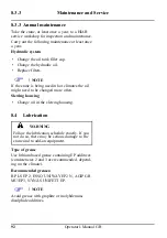
Page 90: ...ment Maintain all add on equipment auxiliary equipment etc according to the instructions supplied with it Oil tank level To check the level in the oil tank Place the vehicle on level ground with the crane in transport position If necessary top up Slewing housing oil level Check the oil level in the slewing housing If necessary top up 8 3 2 Monthly inspection and mainte nance In addition to the dai...

Page 91: ...olts and screw fixings Check that bolt and screw fixings are tight ened Cables and sensors on the boom system Check that these are in good condition Lubrication schedule Carry out the lubrication according to the instructions Hydraulic system Check that the hydraulic pump attachment screws are tightened Check if the oil in the hydraulic system needs to be changed Add on equipment etc Maintain all ...

Page 92: ...es the oil might need to be changed more often Slewing housing Change oil in the slewing housing 8 4 Lubrication WARNING Follow the lubrication schedule exactly If you not do so there may be serious damage to the crane and to add on equipment Type of grease Use lithium based grease containing EP additives consistencies 2 and 3 are recommended depend ing on the climate Recommended greases BP LS EP ...

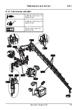
Page 93: ...Maintenance and Service 8 4 1 8 4 1 Lubrication schedule Lubricate after every 16 hours of use Lubricate after every 50 hours of use Grease after every 50 hours of use Operator s Manual GB 93 ...

Page 94: ...e pads Extend all the extensions completely Lubricate through the holes Retract the extensions Upper slide pads Extend extensions with load in order to create enough clearance Lubricate Lower slide pads Extend extensions without load and push slightly against the ground in order to create enough clearance Lubricate 94 Operator s Manual GB ...

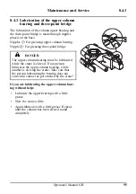
Page 95: ... upper column bearing must be lubricated while the crane is slewed If one person lubricates the upper column bearing while another is slewing the crane Take care that the person lubricating the bearing does not come into contact or get crushed by the crane If you are lubricating the upper column bear ing without help Lubricate the upper bearing with a little grease Slew the crane a little Again lu...

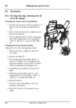
Page 96: ...0 Changing oil in the slewing housing Change the oil in the slewing house yearly 1 Remove the hose coupling from the level glass 2 Remove the plug 3 The slewing housing contains about 13 litres 3 43 gallon Use a container with sufficient capacity to receive the oil Drain off the oil through the filling hose 4 Attach the hose coupling to the level glass 5 Refill through the filling hole with transm...

Page 97: ...he o rings and gaskets Replace if necessary 4 Fit the new cartridge 5 Replace the cover NOTE Check that the cover is properly fitted 8 5 3 Replacing the cartridge in the pressure reduction filter WARNING Dirt will damage the hydraulic system 1 Clean the immediate surroundings of the pressure filter 2 Dismantle the filter housing 3 Remove the cartridge 4 Clean the filter housing 5 Fit a new cartrid...

Page 98: ...Take care that the temperature of the oil does not exceed the point where you can handle it safely If this occurs allow the oil to cool before moving to the next step 2 Suitable eye and hand protection must be worn while carrying out this operation and if there is a risk for inhalation of oil mist a mask as well WARNING Inhalation of oil mist Contact a doctor Skin contact Remove polluted clothing ...

Page 99: ...illing the oil tank with hydraulic oil The oil used for filling must be clean Do not mix different oils Hydraulic oil that is approved for HIAB products must comply with one of the following standards or equivalents DIN 51524 part 3 SS 15 54 34 ISO 11158 HV Suppliers of hydraulic oil must verify that the quality and performance of the oil complies with the above standards When changing from minera...

Page 100: ...recommend an oil working tem perature below 70 C If necessary consider an oil cooler or heater NOTE When working in artic condition consider an oil with lower viscosity than the 32 oil in the table above Environmentally Friendly Oil The environmentally friendly oils recommended for HIAB products are ester based synthetic hydraulic fluids synthetic ester NOTE Vegetable oils do not meet HIAB s requi...

Page 101: ...fter working on the hydraulic system if your crane works slowly or jerkily WARNING Air in the hydraulic system can lead to faults and damage To bleed air from the hydraulic system pro ceed as follows Move each crane cylinder and each hydraulically operated piece of add on equipment at least twice to its end positions slowly Operator s Manual GB 101 ...

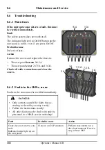
Page 102: ...anel bottom 2x15A The user panel cover 2x7 5A and 3x3A Check all cable connections and close the covers 8 6 2 Faults in the HiPro crane Faults in the crane must be rectified immediately DANGER Only correct yourself the faults that ac cording to the table you may rectify Follow the instructions exactly All other faults may be dealt with only by personnel in a HIAB service workshop Fault Probable ca...

Page 103: ... Clear the blockage or re a noise Three causes is blocked place the entire filler cap Warning Stop using the Oil level in the tank is too Top up the oil tank and crane immediately low bleed the hydraulic system The pump is faulty Go to a HIAB service work shop The stabiliser extensions do The extensions are still Unlock the extensions not slide out locked Hydraulic fault Go to a HIAB service work ...

Page 104: ...ernal Display option Placing The unit shall be placed under the plastic cover together with the SPACE box where it is pro tected from direct water splash Start up The External display automatically starts when the SPACE system is started Operating modes The display has three basic operating modes 1 Use time mode default 2 Error display mode 3 Config mode Use time mode default By default the displa...

Page 105: ... The number of active errors and a dot Each active error in turn Blank display if no errors Start over Press the button again to return to Use time mode Example 3 active errors 003 014 and 028 Clear errors In Error display mode errors can be cleared as in SPACE terminal by pressing the button for 2 seconds until the clear errors symbol is shown in the display Operator s Manual GB 105 ...

Page 106: ...crane s raw materials can be recycled Follow the regulations of the local authorities Oil and grease must not be spilled on to the ground or released into the environment Drain the oil from hydraulic cylinders valves and hoses Sort the waste Deliver the metal parts for recycling for reuse as raw material These are load bearing struc tures manufactured from steel or cast iron hydraulic cylinders an...

Page 107: ...ydraulic cylinder seals lights small plastic and rubber parts Hazardous waste is delivered to a collection point for hazardous waste oils hydraulic oil transmission oil from the slewing system solid lubricants greases from the joints and journal bearings other waste containing oils and greases hy draulic oil filters Operator s Manual GB 107 ...

Page 108: ...ion The Technical Data document shows diagrams and technical information about your specific crane The enclosed Technical Data printed out by the installer should be stored together with this Operator s manual 108 Operator s Manual GB ...

Reviews: