kg
xx
x x
xxx
8 m
7
6
5
4
3
2
1
0
- 1
- 2
- 3
- 4
0 1 2 3 4 5 6 m
1820
1065
725
550
430
22
Safety precautions and warnings
Operator's Manual GB
3.2.3
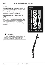
Load diagram
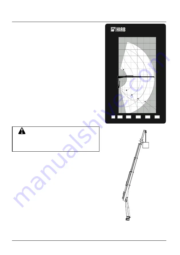
The load diagrams are placed on the column and
show the maximum loads your crane may lift in
the entire working zone (manual extensions ex-
cluded). The load diagram drawing will also be
found in the enclosed Technical Data.
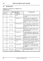
The white area is the working zone of the
crane.
The load curves show the maximum load that
may be lifted at a given reach and height. For a
given maximum load, the possible working zone
is to the left of the load curve. The lifting
capacity for some cranes is limited in the high
lifting area.
WARNING
Care must be taken when handling loads in the
high lifting area, so the load/tool does not
come into contact with the boom system.


