background image

HIAB L-HiPro
145/165/195/235

Operator's Manual GB

This operator's manual is an Original Instruction and applies to cranes with serial number from:

BL145HP00001,  BL165HP00001, BL195HP00001, BL235HP00001

2021-02

Summary of Contents for L-HiPro 145

Page 1: ...AB L HiPro 145 165 195 235 Operator s Manual GB This operator s manual is an Original Instruction and applies to cranes with serial number from BL145HP00001 BL165HP00001 BL195HP00001 BL235HP00001 2021 02 ...

Page 2: ...elf with your crane before you start to use it Help us to improve this manual Please send your comments and suggestions to documentation hiab com This manual includes interactive contents Download the Hiab AR App for the interactive content in this manual Look for the AR symbol Use your device to scan the image next to the symbol The interactive contents in the Hiab AR App will display suggestions...

Page 3: ... 3 3 1 Noise declaration 18 3 3 2 Signs on the crane 19 3 3 3 Maximum load AR 19 3 3 4 Maximum load moment 21 3 4 Signals when using a crane AR 23 3 5 Use of the crane 26 3 5 1 Preparations for use 28 3 5 2 Crane operation 29 3 5 3 Service platform option 34 3 5 4 Driving with the crane 35 3 5 5 Use of lifting equipment 36 3 5 6 Use of demountable cranes 37 3 5 7 Ending crane operation 37 4 The Hi...

Page 4: ... 6 1 5 APO Automatic power off 76 6 1 6 ADO Automatic Dumping of Oil 76 6 1 7 ASC Automatic Speed Control 76 6 1 8 ADC Automatic Duty Control 77 6 1 9 PFD Pump flow distribution 77 6 1 10 Slewing sector option 77 6 1 11 LSS V Load stabilising system vertical Option 78 6 2 OLP Overload protection 78 6 2 1 OLP indications on the controller 79 6 3 To release OLP 80 7 Ending crane operation 82 7 1 Ope...

Page 5: ...8 8 Troubleshooting 109 8 8 1 Main fuses 109 8 8 2 Faults on the crane 110 8 8 3 Display option 113 8 8 4 Error codes 114 8 8 5 Gateway connection box option 116 9 Decommissioning 118 9 1 Decommissioning a crane 118 10 Technical Data 120 10 1 Load plate table 120 10 2 Identification of the loader crane 121 10 3 Abbreviations 121 10 4 Daily inspection checklist 122 10 5 Monthly inspection checklist...

Page 6: ...This page is intentionally left blank HIAB L HiPro 145 165 195 235 ...

Page 7: ...al for your crane carefully it could lead to fatal accidents or serious damage Therefore you should Study the entire Operator s Manual carefully Study the operating manuals for other add on equipment if fitted Use the crane only after having done so Follow the directions for use operation and maintenance of the crane and add on equipment exactly Store the Technical Data and manuals from the Instal...

Page 8: ...fere with the Connectivity or the Information Any intellectual property rights or other right and title in and to the Connectivity features and the Information and all their further developments shall at all times be and remain the exclusive property of Hiab 1 2 Cleanliness certificate All Hiab equipment has been tested and certified at the factory according to the Hiab Standard C250 52 that defin...

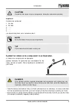
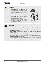
Page 9: ...ane but are an option Not all option are available for your crane DANGER Only persons with the requisite knowledge and experience with cranes may use the crane Never operate the crane when you are sick tired under the influence of medicines alcohol or other drugs Take the delivery instructions from your Hiab authorised service workshop or receive instruction from an experienced person from your ow...

Page 10: ...ns or bearings with a high pressure jet cleaner It could cause damage Never expose the electronic system to high electrical voltages This could damage the control system Never immerse the controller in water or other liquid This will make the controller unusable If your crane is equipped with add on lifting equipment hoist rotator etc The operation of the crane with add on lifting equipment can di...

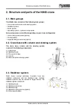
Page 11: ...ewing system The crane base column and the slewing system consist of the following components 1 Crane base 2 Stabiliser beam 3 Three point bridge 4 Column 5 Rack and pinion slewing system 2 3 Stabiliser system HIAB cranes except stationary mounted have two stabiliser extensions and two stabiliser legs Auxiliary stabiliser systems may be needed for bigger cranes The stabiliser system consists of 1 ...

Page 12: ...ystem Hooks option Different hooks can be mounted depending on the crane model DANGER Never exceed the maximum permissible loading of the hook Separate lifting accessories option Separate lifting accessories help to make or use a slinging device shackles eye bolts etc 1 2 3 Structure and parts of the HIAB crane 12 HIAB L HiPro 145 165 195 235 ...

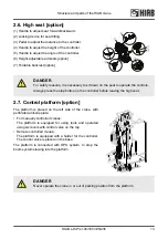
Page 13: ...r before leaving the high seat 2 7 Control platform option The platform is placed on the left side of the crane with perforated anti slip plate For manually controlled cranes The platform is equipped for using tools and operated using six levers with control valve on the top Remote controlled cranes The platform is equipped with a holder for the controller The control valve is placed on the base T...

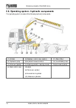
Page 14: ...iser control valve option 11 Return filter 2 Hydraulic pump 6 Hydraulic hoses and lines 12 Load holding valve 3 Oil cooler option 7 Slewing cylinders Slewing motors Pressure filter option 4 Main control valve Actuators 8 First boom cylinder 9 Second boom cylinder 10 Extension cylinder s Structure and parts of the HIAB crane 14 HIAB L HiPro 145 165 195 235 ...

Page 15: ...switched off and you operate a particular crane function To operate a hydraulic cylinder equipped with a load holding valve an opening pressure is required 2 10 Description of HIAB L HiPro The HIAB L HiPro 145 L HiPro 165 L HiPro 195 L HiPro 235 are compact fully hydraulically operated loader cranes Stress history class S2 according to EN 13001 1 The crane type and the manufacturer are marked on t...

Page 16: ...ne will behave unpredictably Never use the crane during a thunderstorm Never use the crane at temperatures below 40 C 40 F as the steel s properties deteriorate below this temperature WARNING At temperatures below 0 C 32 F Do not touch the operating levers during the first few minutes When starting in cold weather the wear on the hydraulic system is greater than at normal working temperatures To g...

Page 17: ...lty 7 13 9 17 1 Severe wind Entire trees move the wind causes difficulty when you walk into it 8 17 2 20 7 Stormy wind Twigs break off walking is difficult 9 20 8 24 4 Storm Causes superficial damage to buildings chimney pots roof tiles and TV antennae are blown off 10 24 5 28 4 Severe storm Uprooted trees considerable damage to buildings etc occurs infrequently on land 11 28 5 32 6 Very severe st...

Page 18: ...ccessories in strong currents such as rivers Loading cargo that is partially loaded or fastened by other means without making sure the capacity of the crane is enough for the entire load Any duty which implies Pressure against the ground unless the crane is specifically prepared for this Push pull with the boom system against any type of obstacle wall ground Using the JIB upside down e g work unde...

Page 19: ...erent positions The lifting capacity of your crane determines the maximum load your crane may lift within its working zone However take careful note the greater the operating radius of the crane the lower the lifting capacity will be because of the weight of the boom system itself The load plate and the load diagram on your crane show the maximum loads you may lift in the operating reach of your c...

Page 20: ...ANGER Never exceed the maximum weight on the load plate Load diagram The load diagrams are placed on the column and show the maximum loads your crane JIB if fitted hoist if fitted may lift in the entire working zone manual extensions excluded The load diagram drawing will also be found in the enclosed Technical Data The white area is the working zone of the crane The load curves show the maximum l...

Page 21: ...ximum load moment lifting capacity the OLP gives a warning and locks any crane movement that will increase the load moment This is known as an OLP situation If the 2nd boom is raised the following movements are locked 1st boom down up 2nd boom down extension boom out If the 2nd boom is down the following movements are locked 1st boom up 2nd boom up extension boom out 1st boom down certain crane ty...

Page 22: ...than 90 do not hang the slings directly on the hook Use a ring hanging from the hook to attach the sling Working close to the load Always try to lift the load with the extension boom retracted however not completely The crane then has the greatest lifting capacity Place the vehicle as close as possible to the load Working below ground level If you have to load or unload below the level of the grou...

Page 23: ... quickly 3 4 Signals when using a crane AR DANGER If it is not possible to see the load and the entire working area clearly the crane operator is obliged to follow the instructions and signals given by a qualified person qualified The country specific regulations for crane operator signals are to be used Signals in this manual give a number of standard signals that can be used Lift Raised arm and ...

Page 24: ...short movement Place the hands a very short distance apart with the palms facing each other The hands may be held either horizontally or vertically The next movement may be Lift lower move the lifting gear change the reach or turn Change the reach Signal with your hands Sideways movement outwards with both hands Thumbs outwards Sideways movement inwards with both hands Thumbs inwards Safety precau...

Page 25: ... shoulder height with the palms facing downwards Close the tool Move both hands close together Lift the open tool a little Extend both arms at shoulder height with the palms facing upwards Make vertical movements with both arms outstretched Safety precautions and warnings HIAB L HiPro 145 165 195 235 25 ...

Page 26: ... undermined Look out for sewers cellars excavations etc The stabiliser legs must not be able to sink in Use support plates that are large and firm enough for your crane The plates must not bend under load Check that the support plate as it comes under load is not pushed into the ground Ensure you can see the stabiliser legs and stabiliser extensions when you are operating them Do not lower the sta...

Page 27: ...gs on the ground Do not raise the vehicle with the stabiliser legs If you raise the vehicle with the stabiliser legs this may damage the stabiliser legs Check that the add on lifting accessories and separate lifting accessories are in good order Add on lifting accessories are sometimes fitted on the crane hoist JIB or placed between the boom tip and the load grapple rotator Separate lifting access...

Page 28: ...in the following minimum distances between the crane and overhead electricity lines unless otherwise prescribed by national rules Minimum distance between crane and overhead electricity lines Voltage V Minimum distance to an insulated conductor Minimum distance to an uninsulated conductor 500 V 0 5 m 2 m 500 40000 V 1 5 m 4 m 40000 V 2 0 m 6 m Voltages are found up to 500 V to buildings 500 40000 ...

Page 29: ...on the crane that were specifically made to help the operator to go into or out from the control station 3 5 2 Crane operation DANGER Your crane has a control system The control system will help you to work safely Nevertheless you remain responsible for safe use of the crane Therefore always work according to the operating instructions In an emergency situation push immediately any of the emergenc...

Page 30: ... person assisting you know these signals Pay attention to the safety of the person giving the signals Never move the vehicle if you have a freely suspended load on the crane Never walk or stand under a suspended load During operation never stand below the boom system or load Do not slew the crane nor lift the first boom nor lift the second boom into their ends positions at full speed This can dama...

Page 31: ...boom system is in a high position first boom above 70 do not allow the boom to lower at full speed The crane could go into an uncontrolled movement Be careful if in particular the OLP gives an early warning When loading the vehicle Take the load off the stabiliser legs by withdrawing them slightly The stabiliser legs must remain in light contact with the ground CAUTION Operate the crane using smoo...

Page 32: ...reaching the slewing stops B NOTE Remote controlled cranes with a slewing sensor will reduce the slewing speed automatically in the area A but they will not stop automatically before reaching the slewing stops B CAUTION Repeated rotation of the crane against the slewing stops during operation can cause major crane base damage If this operation happens it will be considered as a misuse of the crane...

Page 33: ...ed the resulting angle between the hydraulic fork attachment and the boom tip can lead to collision between the boom tip and rotator hoses To avoid possible collision between the boom tip and rotator hoses 1 Elevate the 1st boom as necessary nearly full elevation in close range positions 2 Use the 2nd boom extensions to reach the position needed Safety precautions and warnings HIAB L HiPro 145 165...

Page 34: ...tform option DANGER Never operate the crane while standing on the service platform The platform is only to be used when performing maintenance on the crane Safety precautions and warnings 34 HIAB L HiPro 145 165 195 235 ...

Page 35: ...system must be switched off Pay attention to the width and height of the crane in the transport position The crane has to stay within the width of the truck Make sure the stowed crane can not hit bridges tunnels etc Pay attention to overhead power lines Make sure that no part of the crane ever comes in contact with overhead power lines For further instructions see vehicle s manual s Safety precaut...

Page 36: ...hen you are working on the crane After the lifting accessories have been fitted 1 Check that the lifting accessories are securely fixed 2 Only after this should you use your crane WARNING Always insert the locking pin in the shaft for all the attachments on the tip of the crane hook top roller pulleys Do it in the same direction as shown in the picture WARNING If you attach detach equipment to fro...

Page 37: ...ng demounting the crane on off the vehicle Roughly handling can seriously damage the crane or the vehicle 3 5 7 Ending crane operation DANGER Always end crane operation as follows After use always place the crane in the transport position Withdraw the stabiliser legs and stabiliser extensions Check that the locking mechanisms are properly locked Switch off the operating system Disengage the PTO or...

Page 38: ...he crane there are various sensors and indicators which send signals about the crane s load position and movements to a central microprocessor The microprocessor then decides how the crane can be operated and stops reduces prohibited movements speeds according to the following When prohibited movements speeds are approached a warning is given When prohibited movements speeds are reached On remote ...

Page 39: ... workshop 4 3 Components of the control system 1 Main control valve 4 Dump valve 1 7 Lamp pole Option 2 Stabiliser control valve 5 Dump valve 2 option 8 CombiDrive controller Option 3 User panel SPACE X4 UI 6 Pressure reducer filter 9 XSDrive controller Option The HiPro system HIAB L HiPro 145 165 195 235 39 ...

Page 40: ...the functions is customized for each crane The image on the right shows an example of a main control valve functions placed on the base NOTE For remote operated cranes the levers on the main control valve are only for emergency operation FOR EMERGENCY OPERATION ONLY FOR EMERGENCY OPERATION ONLY 4 5 Different stabiliser control valves Different stabiliser control valves that you can find on cranes ...

Page 41: ...ns outward Button 3 is used for OLP release if the crane is in an OLP situation and for disconnecting the automatic dump function Stop button 4 is pushed in an emergency Button 5 is used to sound the crane horn Button 6 activates OLP for manual extensions if fitted Button 7 activates the controller 4 6 1 Indicator LEDs on User Interface 9 8 7 6 1 2 3 4 5 14 14 13 14 14 12 14 14 15 11 10 The HiPro ...

Page 42: ...e crane VSL or stabiliser leg Green light flashing Critical error Manual extensions 4 Green light on Manual extension mode is active Remote control 5 Green light on Remote control is active Green light flashing Button for remote control has been pressed waiting for connection to hand unit Red light on Radio interference Parking control 6 Blue light on Slew is in parking position Service 7 Green li...

Page 43: ...ion Stability sector 14 Green light on regardless of the situation Cylinder pressure 15 1 of 4 green light on 50 pressure 2 of 4 green light on 70 pressure 3 of 4 red blinking light 90 pressure 4 of 4 red light on 100 pressure 4 of 4 red running light OLP release activated LED test for the User Interface see Daily inspection Standard functions and symbols The order of the functions is customized f...

Page 44: ... and the oil is returned directly to the hydraulic tank As soon as the operator moves a lever the valve closes Dump valve 2 2 Allows operation of the stabiliser extensions and legs only when this valve is activated The dump valve 2 will be placed between the main control valve and the stabiliser control valve The dump valve 2 must be activated from the User Interface before the stabiliser system c...

Page 45: ...adio interference it is possible to change the channel by pushing button There is a maximum of 12 channels available WARNING When the controller is in use stop button released keep a distance of minimum 1 meter between the controller and the crane or truck because of possible electromagnetic interference Cable connection option The cable 2 is intended to be used for short term operation and when p...

Page 46: ...inking OLP Release Low speed 6 Green light on Reduced speed For normal speed see section Buttons Cylinder pressure LEDs 7 Lower LEDs green light on 70 of maximum pressure Lower LEDs red light flashing 90 of maximum pressure Lower and upper LEDs red light 100 of maximum pressure Manual extension 8 Green light on Manual extension activated ADC 9 Green light on Increased capacity ADC mode Menu LEDs 1...

Page 47: ...o activate the manual extension 5 Speed selection At the start you have maximum operational speed Push the button to operate the crane with decreased speed Push it again for maximum speed 6 8 LSS V If the crane has LSS V button 6 activates this feature and button 8 deactivates it 7 Channel shift Push to change radio channel There are 12 channels in total 9 Emergency stop button When you push the b...

Page 48: ... at the same time 3 The 4 LEDs flash at the same time for 5 times 4 LED 1 comes on Start menu 4 10 3 Menus The functions presented in each menu can be customized depending on crane configuration It can be changed by a Hiab Authorized Workshop The table below shows an example Menu 1 Slewing first boom second boom extension boom tools JIB hoist etc Menu 2 option If crane is equipped with extra remot...

Page 49: ... The function corresponding to each lever depends on the configuration of the specific crane The table below shows examples Controller XSDrive levers Controller XSDrive joystick 3 0 3 Controller XSDrive joystick 2 2 2 Controller XSDrive joystick 3 2 3 The HiPro system HIAB L HiPro 145 165 195 235 49 ...

Page 50: ... for a long time Therefore the battery voltage cannot be used to estimate remaining hours of use Battery charger The battery charger is to be fitted in a protected environment preferably in the cab LED 1 is lit continuously when the battery charger is ready for use Place the battery in the charger LED 2 flashes slowly during recharging and has a steady light when the battery is fully charged Charg...

Page 51: ...cable connects to the vehicle at the connector 1 on the front of the decoder When the cable is connected to the controller 2 the centre display shows the symbol for cable operation 4 11 1 Displays The displays are of LCD type and will perform best in temperatures above 10 C At 0 C there is a delay in shifting symbols of approximately 1 sec At 20 C the delay will increase to approximately 8 sec Alt...

Page 52: ...med by pressing the release button only then will the spanner go back to normal size 7 Main menu The text shows which main menu has been selected The number shows which sub menu is active The main menus are CRANE EXTRA and ON OFF 2 Micro Indicates that micro operation has been selected Micro operation changes the sensitivity of the levers as follows At full lever deflection μ50 gives 50 and μ20 gi...

Page 53: ...re not met 11 ADC Automatic Duty Control Indicates that the ADC feature is active 6 Battery capacity The battery symbol shows remaining power in the battery When the symbol begins to flash there is capacity for just a few more minutes When this happens the horn on the crane will sound twice as an indication of low battery 12 13 SAF CTC option SAF function or CTC feature is active CTC SAF Left and ...

Page 54: ...pecific crane Micro mode Push to choose micro mode Push again to choose normal mode 7 3 Menu CRANE Push to choose menu CRANE Stop button Push to deactivate the controller Release to activate 8 4 Menu EXTRA Push to choose menu EXTRA OLP release Push and hold to activate OLP release See section OLP release 9 5 Menu ON OFF Push to choose menu ON OFF Manual extensions Push simultaneously to activate O...

Page 55: ...shows a large locked padlock symbol Unlocking the controller 1 Push and hold button 4 and 5 while the emergency stop button is pushed 2 Keep button 4 and 5 pushed while pulling out the stop button 3 Release button 4 and 5 The controller is ready to use 4 11 3 Menus standard functions and symbols The function of each lever may be the same or different in different menus The left and right displays ...

Page 56: ...as normal With the 2 extra levers on the 8 lever controller it is possible to use the seventh and eighth functions simultaneously with functions 1 6 without shifting CRANE menu CRANE menu button 3 When the operator pulls out the stop button on the controller it always starts in CRANE 1 menu The submenus in CRANE menu are configured in production but can be changed by Hiab service personnel 1 2 3 3...

Page 57: ...troller CRANE MENU 1 2 3 Left side display Centre display Right side display Example of submenus for the 8 lever controller CRANE MENU 1 2 3 Left side display Centre display Right side display The HiPro system HIAB L HiPro 145 165 195 235 57 ...

Page 58: ...down up Auxiliary stabiliser leg 4 down up Crane stabiliser extension 5 out in Crane stabiliser extension 6 out in Auxiliary stabiliser extension 7 out in Auxiliary stabiliser extension 8 out in ON OFF menu button 5 The ON OFF menu includes functions such as engine start stop and throttle The functions are shown as text instead of symbols in the displays A lever may be moved in any direction in or...

Page 59: ... mode crane tip out in 7 1st boom locked when operating CTC mode crane tip out in 8 Manually control the 1st boom up down in CTC mode 9 Manually control the 1st boom down up in CTC mode 10 4 11 4 Battery and battery charger Battery The voltage level of a fully charged battery is approximately 8 4V and it provides about 5 8 hours working time Note that the battery voltage remains between 7 6V and 7...

Page 60: ...hts when the charger is activated 1 and 2 lights during charging 1 and 3 lights when the battery is fully charged Display B Shows the battery voltage 8 4 When the display blinks 0 0 there is error in the battery Change battery NOTE A charged battery is a concentrated energy source Never store a charged battery in a toolbox or similar where there is a risk of a short due to metal components Used ba...

Page 61: ... bubble is between the two circles the crane inclination is between 0 and 5 α 0º α α 0º α Working with boom system beyond 60 To avoid side deflection and in order to guarantee the safest operation when working with e g Lifting Accessories and or Hoist applications and or JIB MEWP applications the vehicle has to be completely levelled in any direction α 0º NOTE Operating the crane in to and out of ...

Page 62: ...t be in neutral position before start up To start the control system push the On Off button on the User Interface The LED above the button lights up The system will check itself for a few seconds The warning lamps on the stabiliser legs light up How to unfold the high seat option 1 Pull lever 2 to unfold the seat option 2 Pull the top part of the backrest to unfold it 3 Put the controller in its h...

Page 63: ...teady and the warning lamps on the stabiliser legs blink Indications XSDrive The first LED in the LEDs menu starts blinking When communication has been established the LED will give a steady light ready for use Indications CombiDrive Wait is shown on the centre display while radio contact is being established On the decoder LED 1 is lit LED 2 starts to blink When contact has been established CRANE...

Page 64: ...RNING If your vehicle has a front auxiliary stabiliser system with one or two legs make sure that all legs are correctly set to the ground before you start operating the crane Stability sector indication The operator must have a full view of the stabiliser system when operating it To confirm a full view of the stabiliser system button is pushed on the User Interface on the side where the stabilise...

Page 65: ...ane model The maximum permitted ground inclination under the stabiliser leg plate is 5º The maximum load that the stabiliser leg can impose on the ground X Cranes L Cranes Z Cranes S Cranes P kN 128 138 142 148 158 162 178 188 192 135 145 155 165 171 191 145 218 228 232 195 225 235 230 175 248 258 262 288 298 302 220 NOTE Sign that shows the maximum force that the stabiliser legs can apply to the ...

Page 66: ...e vehicle For auxiliary stabiliser system option Repeat the process Manually controlled stabiliser extensions Unlock Stabiliser extension locking devices 2 and 3 Take a firm grip around handle 1 and pull to extend the stabiliser extension and lock with the handle 3 Hydraulically controlled stabiliser extensions Unlock the Stabiliser extension locking device 2 option and extend the stabiliser exten...

Page 67: ...ess of the side 5 2 4 Set the stabiliser legs AR The procedure of setting the stabiliser system differs depending on the type of stabiliser system Repeat the instructions for the stabiliser extension and leg on the other side of the vehicle For auxiliary stabiliser system option Repeat the process WARNING Take care not to lower the stabiliser leg onto your foot NOTE For cranes with VSL the stabili...

Page 68: ...lates DANGER Check that the support plates do not bend or sink into the ground Non tiltable stabiliser legs 1 Make sure that the stabiliser extensions are extended 2 Operate the stabiliser leg downwards until it is set to the ground Starting crane operation 68 HIAB L HiPro 145 165 195 235 ...

Page 69: ...ly tiltable stabiliser legs with gas spring support DANGER Do not stand in the stabiliser leg tilting area 1 Make sure the stabiliser extension is extended and the stabiliser leg can rotate freely of the vehicle 2 Place your right hand on the handle 3 while unlocking the stabiliser leg 4 with your left hand Make sure the leg drops in a controlled movement until it stops Push the handle until the l...

Page 70: ...juries Always keep hands away from moving parts during operation 5 Lock the stabiliser leg lock 1 6 Extend the stabiliser extension to a safe position For manual extension lock the extension 7 Extend the stabiliser leg until it is set to the ground 5 3 Operate the boom system out of transport position WARNING A crane with add on equipment can differ from the operations described in this section Fo...

Page 71: ...ush button on the User Interface to activate remote control 2 If using remote control push button 1 on the controller to change the menu into crane operation NOTE As soon as you have selected remote control operation it is no longer possible to operate the main control valve levers Starting crane operation HIAB L HiPro 145 165 195 235 71 ...

Page 72: ...button to allow second boom and extensions movements DANGER Only use the BDA override to get the crane out of a locked position Operating the crane out of transport position When the angle ß is 135º between the horizontal and second boom second boom and extensions can move without any restrictions Operate the boom system 1 Raise the first boom 1 2 Slew the crane to the working position 2 3 Extend ...

Page 73: ...Starting crane operation HIAB L HiPro 145 165 195 235 73 ...

Page 74: ...on again the crane returns to full speed and the LED goes out When pushing the speed selector button all levers must be in neutral NOTE The crane speed will depend upon the crane functions you are using and how many crane functions you operate at the same time 6 1 2 Controlling the crane speed with the controller CombiDrive At startup the crane speed is set to 100 It is possible to choose between ...

Page 75: ...e OPS system is integrated in the control system and it uses a sensor on the slewing system and tilt indicators on the boom system to indicate the position of the crane It creates a virtual cage around the area where the crane operator stands while manually operating the crane How to operate the crane using CTC 1 Navigate to the menu for CTC NOTE The crane tip will not move until the 1st boom reac...

Page 76: ...tip will not move until the 1st boom reaches its optimum position 6 1 5 APO Automatic power off APO is a feature which automatically switches off the power to the control system It consists of 1 Timeout controlled power off 30 minutes by default 2 Parking brake controlled power off Through the vehicle s parking brake APO offers a safety feature which ensures that the control system is off when the...

Page 77: ...lifting capacity is increased during the complete lifting cycle 6 1 9 PFD Pump flow distribution When operating several functions simultaneously the pump flow may not be sufficient PFD will now take over reducing the speed of all operated functions Uncontrolled movements are thus avoided smooth simultaneous operation is achieved 6 1 10 Slewing sector option Within slewing sector lifting capacity c...

Page 78: ... button 6 to activate and button 8 to deactivate Activate and deactivate LSS V By default with the controller CombiDrive 1 Push the ON OFF button 5 on the remote control CombiDrive with 6 levers Menu 2 ON OFF CombiDrive with 8 levers Menu 1 ON OFF 2 Move the levers according to the text in the display CombiDrive with 6 levers lever 4 activate and lever 5 deactivate CombiDrive with 8 levers lever 7...

Page 79: ...ited function is used all functions will stop The crane will be fully operational as long as only allowed functions are used 6 2 1 OLP indications on the controller XSDrive OLP boom system The cylinder LEDs indicate a percentage of maximum pressure 70 of maximum pressure reached lower LED on each cylinder light green 90 of maximum pressure reached lower LED on each cylinder flash red 100 of maximu...

Page 80: ... before the release operation can be activated again The wait will increase in three steps 30 60 and maximum 90 seconds During each 5 second interval only one function at a time can be operated Extension out cannot be operated at all The 5 second interval starts to count down as you move the lever DANGER Only use the OLP release to get the crane out of a locked position Never use the OLP release t...

Page 81: ...ng light The LED for padlock symbol will blink red OLP release on controller CombiDrive Push and hold the button 9 on the right hand side below the display handle The unlocked padlock will appear in the centre display On the User Interface the cylinder pressure LEDs perform a running light The LED for padlock symbol will blink red 9 During operation HIAB L HiPro 145 165 195 235 81 ...

Page 82: ... During folding of the boom system always operate the crane manually from the position indicated in the figure With remote controlled cranes stay in a safety area while the boom system is moving Operate the boom system 1 Retract the extensions completely 1 2 Slew the crane until the crane is parallel to the vehicle 2 3 Lower the boom system against the vehicle 3 Do not extend the second boom cylin...

Page 83: ...pe of stabiliser leg Repeat the instructions for the stabiliser extension and leg on the other side of the vehicle For auxiliary stabiliser system option Repeat the process DANGER Always ensure that the stabiliser legs and the stabiliser extensions are in transport position and securely locked before moving the vehicle Activate stabiliser operation on the User Interface by pushing button Ending cr...

Page 84: ...rts during operation Manual tiltable stabiliser legs 1 Retract the stabiliser leg completely 2 Unlock the stabiliser leg lock 1 3 Tilt the stabiliser leg manually 4 Lock the stabiliser leg lock 1 5 Retract the stabiliser extension completely DANGER Risk of crushing injuries Always keep hands away from moving parts during operation Ending crane operation 84 HIAB L HiPro 145 165 195 235 ...

Page 85: ...sh the leg up until it reaches parking position 5 Lock the stabiliser leg 6 Retract the stabiliser extension completely Mechanically controlled tiltable stabiliser legs AR 1 Retract the stabiliser leg so it is just free of the ground 2 Unlock the leg 1 Retract the stabiliser leg When 200 mm remains the leg will start to tilt upwards DANGER Risk of crushing injuries Always keep hands away from movi...

Page 86: ... handle 3 Take a firm grip around handle 1 and push to retract the stabiliser extension and lock with the handle 3 Make sure the catcher 2 is securely locked Hydraulically controlled stabiliser extensions Retract the stabiliser extensions with the levers on the valve or the controller depending on your crane configuration Make sure the catcher 2 option is securely locked WARNING Always ensure that...

Page 87: ...er 2 to fold the seat 7 3 Switching off the control system Switch off the control system with the on off button If you are using the remote controller Push the stop button on the controller and switch off the control system Disengage the PTO 7 4 Emergency operation Valve V200 EMERGENCY operation to bring the crane to transport position Do like this Ending crane operation HIAB L HiPro 145 165 195 2...

Page 88: ...ak the security sealing on dump valve 1 1 on the main control valve 3 Use a screw driver or similar and push the knob on dump valve 1 1 4 Check that no unintended movements starts If you get unintended movements then release the knob and contact Hiab service 5 Push the dump valve button and turn 90 degrees until it is blocked 6 Operate the crane to transport position using the levers on the main c...

Page 89: ... until it is blocked 6 Operate the stabiliser extensions and stabiliser legs to transport position using the levers on the stabiliser control valve 7 5 Transport warning option WARNING If you switch off the safety system when stabiliser extensions stabiliser legs are not locked in the transport position and or if the first boom angle exceeds a certain specified angle the indicator LEDs on the UI f...

Page 90: ...ed DANGER After use always put the crane into the transport position When you have to park the boom on the load space or over the load secure the boom and the lifting accessories to prevent any unintentional movement of the crane and the lifting accessories Ending crane operation 90 HIAB L HiPro 145 165 195 235 ...

Page 91: ...Do not replace any hydraulic hoses or lines yourself You can disconnect a hydraulic line or a hose only for specific operator s tasks for example disconnecting the JIB or other accessories 1 Make sure that the cylinders are not at the end of stroke and minimise as much as possible the forces acting on them 2 Switch off the system 3 Disengage the PTO 4 Make sure that you wear the correct personal p...

Page 92: ...ories according to the supplier s instructions WARNING Make sure that faults in the crane are corrected immediately Never correct faults yourself that may only be corrected by a Hiab authorised service workshop Carry out yourself only the service and maintenance work you have the requisite knowledge and experience for Maintenance must be performed by qualified personnel Always use personal protect...

Page 93: ...he Hiab authorised service workshop Long storage of the crane If you need to store your crane for a month or longer do this first 1 Clean it according to the instructions in the section Cleaning of this manual 2 Lubricate it according to the lubrication schedule of this manual 3 Put the crane into transport position and disconnect the power from the vehicle battery 4 Put grease on the exposed pist...

Page 94: ... oil tank Only the cranes surface may be cleaned with a high pressure jet cleaner NOTE Always lubricate after cleaning the crane WARNING Keep the devices to go into the control station handles supports platforms clean from oil grease and dirt to prevent slipping and falling Maintenance and Service 94 HIAB L HiPro 145 165 195 235 ...

Page 95: ...king devices are undamaged and working properly Make sure that the locking devices are properly locked Spirit Level Make sure that the spirit level is clearly visible to the operator and works correctly Shafts shaft lockings bearings and bushings Check that the shafts shaft locking bearings and bushings are undamaged and working properly Stop buttons Check that the Stop buttons are undamaged and w...

Page 96: ...a cloth to wipe away any dirt Before every shift Do an inspection of the general conditions of the Hook 1 for deformation stretched cracked twisted excessive wear and surface damages with significant depth such as from chemicals or heat Do an inspection of the Clevis Link Shaft 3 for damage deformation Do an inspection of the two Spring Roll pins 8 and 9 that are in place and properly retaining th...

Page 97: ...wivels washers nuts pins Lubricate the hook according to the chapter Lubrication of the hooks DANGER In the event of damage or worn to prevent a safety risk Do not use the hook Have the damage repaired immediately by a Hiab authorised service workshop Add on equipment and separate accessories hoist etc Check the cables cable connections the cable guides and the attachment points for the add on equ...

Page 98: ... and connections Make sure that all security seal wires Ex LHV dump valves etc are not broken Always go to contact a Hiab authorised service workshop when the seal wire has been broken Check oil level in the tank If necessary fill to correct level NOTE Always place the vehicle on level ground with the crane in transport position while checking the oil Oil level on the slewing housing Do a check of...

Page 99: ...s Check that cables and sensors are in good condition Lubrication schedule Carry out the lubrication according to the instructions Slewing bearing upper column bearing Check that the slewing bearing upper column bearing is lubricated sufficiently Hydraulic system Check that the hydraulic pump attachment screws are tightened Check if the oil in the hydraulic system needs to be changed or have it te...

Page 100: ...e hook for a new one if the hook is damaged Replace the latch assembly if it is damaged missing or malfunctioning Hook 8 t and 10 t without spring roll pins replace the hook for a new one if the clevis link or split clevis retaining nuts are missing or damaged Hook 10 t with spring roll pins replace the two spring roll pins and the plane bearing for a new ones at least once a year 8 4 Lubrication ...

Page 101: ...se WARNING Personnel should never attempt to work on a crane that is moving Serious injury or death will occur if you try to work on an activated moving crane CAUTION When you use pressure grease pumps open the plastic safety guard of the nipple and close it at the end Greases Use lithium based grease containing EP additives consistencies 2 and 3 are recommended depending on the climate CAUTION Do...

Page 102: ...AR Lubricate after every 16 hours of use Lubricate after every 50 hours of use 1 E link 2 B link Not present on X CLX 218 X DUO 218 X HiDuo 228 and X HiPro 232 with E link Maintenance and Service 102 HIAB L HiPro 145 165 195 235 ...

Page 103: ...completed one turn If you are greasing the upper column bearing with help One person greases the upper column bearing while another carefully slews the crane DANGER Be very careful that the person greasing the bearing does not come into contact or get crushed by the crane Greases Use lithium based grease containing EP additives consistencies 2 and 3 are recommended depending on the climate Do not ...

Page 104: ...IRAX S2 A 80W 90 or equivalent quality CAUTION The oil used for filling must be clean Do not mix different oils a mixture will change the oil properties Oil level checking Measuring stick or level glass Check if the oil level on the measuring stick 1 or on the level glass 2 is between the maximum and minimum levels Oil filling procedure top up procedure Measuring stick or level glass 1 If the oil ...

Page 105: ...th oil up to the max level indicator CAUTION Never fill the tank completely because during operation the volume of the oil could expand as the temperature increases Never use recycled oil Filling the oil tank with hydraulic oil CAUTION The oil used for filling must be clean Do not mix different oils a mixture will change the oil properties Hydraulic oils must have been dealt with according to clea...

Page 106: ... RANDO HDZ46 Agip ARNICA 46 Mobil SHC 526 Where to use them Viscosity of oil The viscosity of the oil is of great importance to achieve high efficiency of the hydraulic system The naming of the oil in the table below 32 46 or 68 tells the viscosity of that oil at 40 C reference temperature Viscosity of oil at 40 C Temperature range 32 25 C to 75 C 46 15 C to 90 C 68 5 C to 90 C The recommended vis...

Page 107: ...ns 2 Operate the crane to parked position 3 Check and top up the oil tank to max level on the tank gauge 4 Bleed the air from the hydraulic system 8 6 Replacement of filters Filter cartridges must be replaced by a Hiab authorised service workshop After the first 50 hours operation Then after every 1000 hours operation Or at least once a year How do you verify if the filter needs a replacement The ...

Page 108: ...ed for a long time WARNING Air in the hydraulic system can lead to faults and damage To bleed the air from the hydraulic system proceed as follows 1 Slowly extend and retract each stabiliser extension to its end position at least two times 2 Slowly extend and retract each stabiliser leg to its end position at least two times 3 Set stabiliser system in working position and operate the crane out of ...

Page 109: ...work at all The indicator light next to On Off button on the User Interface is not lit even if you push On Off Defective fuses 1 Replace faulty fuses in the vehicle standard box relay box See Description Components Fuse Location 2 Check all the cable connections Description Components Fuse Location System main fuse Relay Box Standard Box Oil Cooler 40 A Located on the vehicle where the crane is mo...

Page 110: ...w the instructions exactly All other faults must be corrected by personnel in a Hiab authorised service workshop Fault Probable cause Action Electronic system will not start Parking brake on the truck is not engaged Engage parking brake on the truck The hydraulic pump makes a noise Warning Stop using the crane immediately Oil tank filler breather is clogged Clear the blockage or replace the entire...

Page 111: ...ft ground surface Set again the stabiliser led onto the ground or add an extra support plate between the cylinder and ground Slewing support cylinders do not turn Three way valve failure Go to a Hiab authorised service workshop Irregular slewing movements and unusual noises in cranes with rack and pinion slewing system Insufficient oil in the hydraulic system Top up the oil tank Insufficient oil i...

Page 112: ...stem has detected a fault Contact a Hiab authorised service workshop Cane performance when operating it with the controller is unsatisfactory The pressure reducer filter is clogged Replace the pressure reducer filter Boom system cannot keep the load height and it goes down by itself Load holding valves on the first boom or second boom damaged Go to a Hiab authorised service workshop Cylinder inter...

Page 113: ...em 8 8 3 Display option The display has three menu items Error codes Timers Counters and VSL Slewing sector These items are shown on the screen when the display is first engaged To be able to select an item press the menu toggle button or the OK button In the bottom left of the screen the name of the item currently highlighted is shown Buttons 1 Main menu button Press to go back to main menu 2 Bac...

Page 114: ...ator of the occurrence When the screen goes back to normal the symbol of the hook is shown in the top right of the screen When deactivating LSS V the screen turns blue again and the hook symbol is shown this time crossed in a red circle The hook symbol in the top right of the screen disappears 8 8 4 Error codes SPACE has many error codes that can help you or Hiab technicians solve some problems wi...

Page 115: ... a Hiab authorised service workshop E056 JIB plug conflict 1 There is probably a short circuit inside the JIB plug Clean the JIB cable connector and the JIB plug 2 Put electric grease on both the connector and the JIB plug 3 Set the system to OFF and then back to ON If you can still see the error go to a Hiab authorised service workshop E186 SAF This error appears only when you move a lever for SA...

Page 116: ...exist in the system the blinking sequence will show them in the same sequence Error code number Blinking sequence Problem Possible cause 1 1 blink The gateway is not able to read the product data this state is not in use in the factory image SPACE is not on The cable between SPACE and the gateway is not connected correctly The gateway is not configured correctly Contact Hiab support 2 2 blinks The...

Page 117: ...starts again Example Several errors exist in the system Error 2 and 3 exist in the system NOTE If error 1 2 and 3 exist in the same time do a check that you have the correct Gateway kit EU for European Union or US for United States Canada and Mexico Maintenance and Service HIAB L HiPro 145 165 195 235 117 ...

Page 118: ... materials can be recycled Follow the regulations of the local authorities Oil and grease must not be spilled on to the ground or released into the environment Drain the oil from hydraulic cylinders valves and hoses Sort the waste Deliver the metal parts for recycling for reuse as raw material These are load bearing structures manufactured from steel or cast iron hydraulic cylinders and lines drai...

Page 119: ... from the joints and journal bearings Other waste containing oils and greases hydraulic oil filters European Union Disposal Information This symbol identifies the parts of your crane that need to be disposed of separately from household waste according to EU legislation When one of these parts reaches the end of its life take it to a collection site designated by local authorities Responsible coll...

Page 120: ... must fill in the valid meters m and kilos kg in this table following instructions given in the Installation instructions m kg The enclosed Technical Data must be stored together with this Operator s manual Technical Data 120 HIAB L HiPro 145 165 195 235 ...

Page 121: ...stem Horizontal Load Stabilising System Horizontal LSS V Load Stabilising System Vertical Load Stabilising System Vertical MEWP Mobile Elevating Work Platform Mobile Elevating Work Platform MSC Manual Speed Control Manual Speed Control MUX Multiplexer Box Multiplexer Box OLP Overload Protection Overload Protection OPS Operator Protection System Operator Protection System PFD Pump Flow Distribution...

Page 122: ... the slewing motors and condition Filters FUNCTIONAL TESTS Stop buttons Levers Controller Horn and LED test If you find a fault that prevents you from operating the crane safely contact a Hiab authorised service workshop Do not try to repair the fault it can cause you injury or you can damage the equipment Permission to reproduce this checklist is granted however please note that only the original...

Page 123: ...fault that prevents you from operating the crane safely contact a Hiab authorised service workshop Do not try to repair the fault it can cause you injury or you can damage the equipment Permission to reproduce this checklist is granted however please note that only the original document owned by Hiab will contain necessary amendments and updates Hiab shall not be held liable if the copy in your po...

Page 124: ...This page is intentionally left blank HIAB L HiPro 145 165 195 235 ...

Reviews: