USER'S GUIDE R18 AXIAL FAN , Iss: 6.05.2021
Recommended cable for power supply is a heat resistant PVC or other cable of appropriate quality (105°C) acc. to IEC 60227-5, e.g. H05V2V2-F, 4G
1.5 mm² (min.1.0 mm² - max. 2.5 mm² for stranded leads or max. 2.5mm² for solid conductors), outer diameter 6.0 - 11mm. Power supply cable could
include also additional leads for alarm circuit, e.g. H05V2V2-F, 6G 1 mm².
Recommended cable for alarm circuit is an ordinary PVC cable acc. to IEC 60227-5, e.g. H05V2V2-F, 2X 1 mm² (min.2X 0.50mm² - max. 2X 1.5mm²),
outer diameter 5.0 - 9.5mm.
Recommended cable for control circuit is an ordinary PVC cable, e.g. H05VV-F, 5X 0,5 mm² (min. 0,25 mm² - max. 0,75 mm² ) , no longer than 2m,
outer diameter 6.0 - 11mm and must be sufficient separated and isolated from the supply circuit and alarm circuit leads. No cable crossing inside the
connection box is allowed.
The connection cables must be prepared before opening the terminal cover. Only open the terminal cover in dry conditions and make sure that the
remains of conductors do not fall into the terminal compartment.
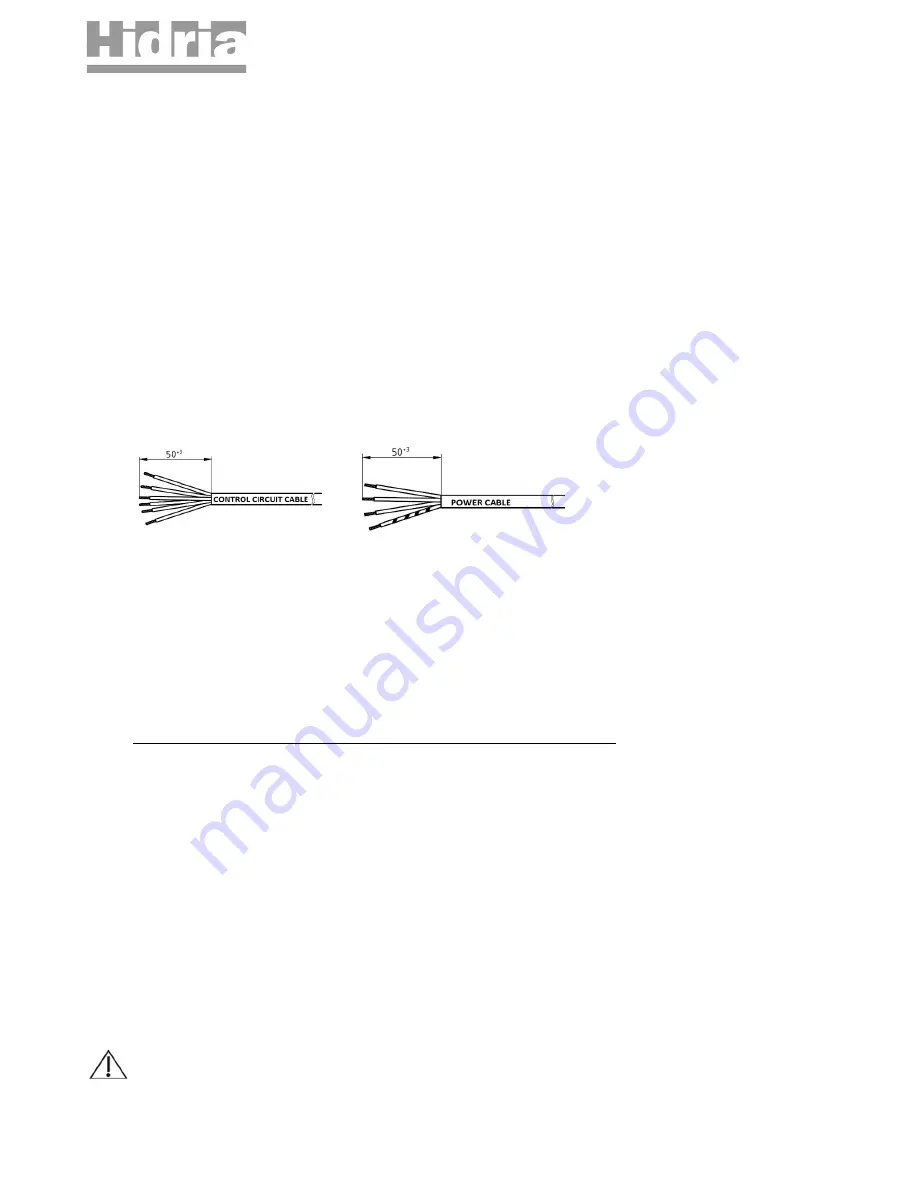
Follow the instructions for preparing the connecting cables as shown in the figure below. Cable sheath needs to stripped in the length of 50 - 60mm.
Ends of stranded wires needs to be provided with insulated ferrule (pin) length 8-10mm.
The fan is equipped with push-in spring terminals type PHOENIX SPTA or eqvivalent, that allow very easy connection.
A screwdriver of 0.6X3.5mm is necessary tool to remove conductor from the mains terminals and a screwdriver of 2.5x0.5mm is necessary tool to
remove conductor from the control circuit terminals.
Fan performed with terminal box is as supplied fitted with a sealing plug in the cable glands as a preventive against ingress of water or moisture inside
the terminal box. If the cable is not installed through the cable gland, sealing plug must remain in the gland! Connection box screws have to be
tightened with torque of 2,0Nm - 2,5Nm.
Secure connection cable to the fan guard grill or to the motor holder with cable fasteners so that the water flows away from the cable and cable gland.
Try to maintain as much distance between supply and control cable as possible (recommended distance > 5cm).
Cable-end of the fan must be connected in a dry environment to prevent that water penetrate through cable into motor housing.
Where the fan is installed in shaft-horizontal position, the cable exit on the motor must be in down position.
Before putting into operation, check the resistance of protective-earth circuit of the entire application. Cross-sectional area and material of PE conductor
may be the same as cross-sectional of phase conductor or see guide regarding PE conductor : standard EN 61800-5-1.
A second protective earthing conductor must be installed to ensure requirements of standard "
EN 61800-5-1 , 4.3.5.5.2 Touch current in case of failure
of protective earthing conductor
". For that purpose an additional M4 of 12mm depth hole or additional PE terminal is provided on motor housing and
marked with PE symbol. More information about dimensions of second PE conductor please find in guidelines of mentioned EN or equivalent standard
(a cross-section of second Cu conductor should never be less than 2.5mm
2
).
CONNECTING DIAGRAM : See appended technical drawing - CONNECTING DIAGRAM 0302-0-0023
POWER SUPPLY : L1, L2, L3, PE
CONTROL CIRCUIT:
Control circuit is SELV isolated from main power supply (including an external power supply for sensors).
Enable: I01 - +10V
Modbus : RS A - RS B
0-10V analog input : 0..10V - COM
Sensor supply : +10V - COM
Slave control : OUT - GND
Alarm relay: COM - NC (SELV)
The device is compatible with Modbus protocol RTU. Please read additional instructions about Hidria EC Modbus parameters.
WARNING : Leakage current exceeds 3.5mA.
Short circuit rating: <10kA .
© Copyright HIDRIA d.o.o., All rights reserved. Document is subject to change without prior notification.
6 / 10


