background image

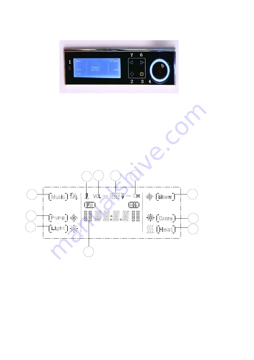
Panel 2 


1


Signal receiving hole                                                        5

  Function confirmed 

2


    Menu/functionswitch/Station storage                            6

  Turn right 

3


    Power                                                                              7

  Turn left 

4


  Adjusting button 


The LCD shows the following information 

1

2

3

4

7

11 10

9

8

6

5


1) Icon and condition of Radio/Audio                    7) Icon and condition Blower 

2) Icon and condition of Pump                                  8) Frequency English icon 

3) Icon and condition of Lamp                                  9) Numerical value of Volume/Frequency 

4) FM hopping state                                                      10) Volume English icon 

5) Icon and condition of Heater                              11) Temperature English icon 

6) Icon and condition of Ozone 


Summary of Contents for KF-618

Page 1: ...Whirlpool Bathtub Instructions of installation and use 1800 900 610MM Single Seat 1800 1200 610MM Double Seat ...

Page 2: ...process 3 3 Instruction of using our products 4 4 Cleaning Maintaining 8 1 Preparations A 1 Check the products and accessories inside the package Only 1 package as below picture Shows Including 1 Pillow 2 2 Water hose for hot and cold water 3 Shower head 4 Shower Hose 5 waste pipe 6 water fall 7 2 cold and hot water switches 8 Change over switch 9 4 conection hose A 2 Tear off the protection plast...

Page 3: ...A 3 Bathtub Drawing 1800 900 610MM Single Seat 1800 1200 610MM Double Seat ...

Page 4: ...ess A 1 Install the change over switch and cold hot water switches Ⅰ Screw off the cover of the Change over switch Ⅱ Screw off the screw and take off the switch Ⅲ Install the change over switch as the below pictures Show ...

Page 5: ...d water switches by the above mentioned procedures Note that the change over switch is in the middle of the 2 hot cold water switches Ⅴ Connect the cold and hot water hoses with the brass connection A 2 Install the waterfall ...

Page 6: ...tall the pillow 3 Instruction of using our products I Instruction of control panel Panel 1 1 Water Pump Surf 7 adjusting plus 2 Blower 8 Frequency button 3 Thermostatic Heating 9 FM radio or CD button 4 Lock 10 adjusting minus 5 Under Water Light 11 Volume button 6 Ozone Sterilization 12 Power ON OFF Button ...

Page 7: ... following information 1 2 3 4 7 11 10 9 8 6 5 1 Icon and condition of Radio Audio 7 Icon and condition Blower 2 Icon and condition of Pump 8 Frequency English icon 3 Icon and condition of Lamp 9 Numerical value of Volume Frequency 4 FM hopping state 10 Volume English icon 5 Icon and condition of Heater 11 Temperature English icon 6 Icon and condition of Ozone ...

Page 8: ...ration with the control panel for 5 minutes all the keys will be locked except LCD displays LOCK When the keys were locked press for 3 seconds the keys will be unlocked after A di icon LOCK disappear When the keys were unlocked press for 3 seconds the keys will be locked after a di LCD displays LOCK 7 Blower When the system is on press this button to start the blower press again to power off 8 Wat...

Page 9: ...unction button works there is a sound of di di 2 Adjusting button Adjusting button can turn both right and left It takes cell as unit turn on cell one operation was made Turn right or turn left can operate the functions 3 Note of Icons and cursor Icons like are directing icons all the directing icons are displaying on LCD after power on is cursor which shows only one on LCD Turn right moves upward...

Page 10: ... later 8 Water pump The water checking device of this controller protects the water pump from burning out When the water level achieves the setting value move to press to start the pump on LCD blinks press again to stop the pump on LCD stops blink When the water level lower than the setting value pump stops working When the water level lower than the setting value pump stops working automatically ...

Page 11: ...or CD function is on press till blinks The tuning steps are 40 with each step 2 dB and the volume adjusting range shall be 80dB 0dB During the tuning LCD shall flash to display the volume value and the finally adjusted value shall be the set value Press the icon once the volume value shall be increased by 2dB When press the icon for more than 2s the volume shall be increased at the speed of 10dB s...

Page 12: ... find the overflow and drain are blocked by dirties screw it off and clean 5 Gold and chrome finished accessories don t need much wiping 6 Don t clean the bathtub with rough tools or detergent with chemicals solvents 7 When you finish using the bathtub drain and power off 8 Don t hammer and carve the shower room with blunt object or some thing very sharp 9 Filling the whirlpool fully with 40 warm ...

Reviews: