


3. Installation
Only simple tools (screwdriver and wrenches), plus pipe sealant for plastic adapters, are required to install and
service the filter.
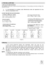
1) The filter must be placed on level, very firm,ground. Position the filter so that the piping connections, control
valve and winter drain are convenient and accessible for operation, service and winterizing.
2) Assemble the Pump to the platform base. The adapters must now be installed to connect the pump/filter
system.
a. Apply Teflon pipe sealant tape or Permatex No. 2 sealant to straight adapter. Screw adapter into pump
discharge port. (Do not over tighten.)
b. Apply Teflon pipe sealant tape or Permatex No. 2 sealant to elbow adapter. Screw adapter securely into
opening in control valve marked Pump.(Do not over tighten.)
3) Loading sand media. Filter sand media is loaded through the top opening of the filter.
a. Loosen flange clamp and remove Filter Control Valve (if previously installed).
b. Cap internal pipe with sand shield to preventsand from entering it. Be sure pipe is securely in place in
bottom under drain hub.
c.We recommend filling tank approximately 1/2 way with water to provide a cushioning effect when the filter
sand is poured in. This helps protect the under drain laterals from excessive shock.(Be sure the winter drain
cap is securely in place on drain pipe)
d.Carefully pour in correct amount and grade of filter sand, as specified.(Be sure center pipe remains centered
in opening.)Sand surface should be leveled and should come to about the middle of the filter tank. Remove
sand shield from internal pipe.
4) Assemble Filter control Valve to filter tank.
a.Place valve flange clamp around neck of tank. Do not tighten. Wipe filter flange dean.
b.Insert Filter Control Valve (with valve/flange 0-ring in place
)
into the tank neck, taking care that the center
pipe slips into the hole in the bottom of the valve. Place clamp around valve flange and tank flange just enough
so that the valve may be rotated on tank for final positioning.
c.carefully screw pressure gauge, with pipe tape, into 1/4 trapped hole in valve body. Do not over tighten.
d.Place hose clamps on clear hose and fit hose over staight and elbow adapters and secure with clamps. If it
is difficult to fit hose over adapters, place hose in hot water for several minutes. Connect pump to control valve
opening marked PUMP according to instructions. After connections are made,tighten valve flange clamp with
screwdriver, tapping around clamp with screwdriver handle to help seat valve flange clamp.
To prevent breakage and damage to pump and control valve, use only pipes sealants
specifically formulated for plastics. Do not over tighten fittings or adapters.
5) Connect pool return line to control valve opening marked RETURN. Complete suction line and waste
plumbing connections.
6) Refer to Pump owners Guide for electrical connections.
7) Check all connections including winter drain cap for leaks.
Check to confirm all laterals are in the down position before loading with sand.


