background image

e13
021584

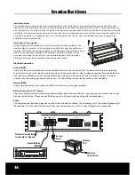
FUSE

GND

REM BATT+ 12V

POWER INPUT

SPEAKER OUTPUT

+   CH3   –

+   CH4   –

+ MONO   BRIDGED –

+   CH1   –

+   CH2   –

14

Installation

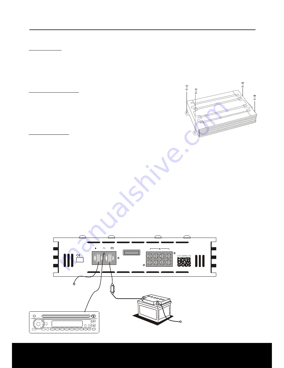
Battery

12 V

In-Line

Fuse

Ground-

Connection

Ground-Connection

to vehicle's chassis

Remote Wire

 (REM)

Installation Notes

The amplifier is generally mounted in the rear trunk area but can be mounted in any convenient area such as beneath a seat. 

Please be sure to locate this unit where you have reasonable air circulation and protection from moisture. When considering the 

mounting location you should minimize the length of the power and speaker leads. Minimizing both leads will yield a more reliable 

installation. It is also important to ensure that the heat sink fins are not against a panel or a surface, preventing air circulation. Do 

not install the amplifier on a subwoofer box or on vibrating parts of the vehicle, since the vibrations can cause damage to the 

amplifiers electrical components.

Installation of the amplifier

Before starting with the installlation, mount the provided mounting brackets on the 

amplifier. Mark the location for the mounting screw holes by using the amplifier as a 

template. Drill holes at the marked locations as and firmly fasten the amplifier in place 

with the mounting screws supplied in the accessory kit. Before drilling or cutting 

any holes, investigate the layout of your automobile thoroughly. Take care when 

working near the gas lines or hydraulic lines and electrical wiring.

Electrical Connection

Ground (GND)

This wire is the electrical ground and must be fastened securely to the vehicle chassis. The best method is to use a threading 

sheet metal screw since the threads cut into bare metal. Ensure that all paint or other insulationis removed from around the hole 

area, and using self tapping screw, securely affix the bare wire ends to the vehicle chassis. Use as short a piece of cable as 

possible - use the same gauge as was used for the +12V cable. Make sure that the connection is safe and stable.

Remote (REM)

Connect the remote wire of your headunit with the remote turn-on of the power amplifier.

Battery Connection (+12V Power)

This wire is usually connected directly to the positive battery terminal. Ensure that the + power supply wire is fused via an in-line 

fuse near by the battery. Please use a sufficient gauge (min. 25 sqmm) with spade lug with insulating sleeve.

Fuses

The integrated amplifier fuses protect the units from short circuit and overload. The fuse rating is for 4 Ohm loads (impedance) of 

the speakers, for 2 Ohm loads the fuses may have to get increased by up to 50% in case of higher power consumption.

Summary of Contents for Zeus ZXi 4000 MkII

Page 1: ...ZXi 4000 MkII ZXi 4400 MkII ZXi 6000 MkII ZXi 6400 MkII Bedienungsanleitung Owner s Manual ZXi 9000 MkII ZXi 9400 ...

Page 2: ...o Subwoofer gebrückt 4 Kanal Verstärker ZXi 4400 ZXi 6400 ZXi 9400 Funktionen Bedienelemente Lautsprecher Cinchanschlüsse 4 Kanal Modus Stereo Front und Hecksystem Lautsprecher Cinchanschlüsse 2 Kanal Modus 2 Mono Subwoofer gebrückt Lautsprecher Cinchanschlüsse 3 Kanal Modus Stereo und 1 Subwoofer gebrückt Fehlerbehebung Technische Daten 2 Inhaltsverzeichnis 3 4 5 6 7 8 9 10 11 12 OWNER S MANUAL i...

Page 3: ...Sie zum Anschluss ein ausreichend dimensioniertes Stromkabel min 25qmm und installieren Sie eine zusätzliche Kabel Sicherung Diese sollte um absolute Betriebssicherheit zu gewährleisten möglichst nahe an der Batterie sein Einschaltleitung REM Verbinden Sie den Schaltausgang z B für automatische Antenne des Steuergerätes Autoradio mit dem Remote Anschluss des Verstärkers Dadurch schaltet sich der V...

Page 4: ... ist der Verstärker betriebsbereit Protect LED Leuchtet diese LED rot kann dies folgende Gründe haben a Überhitzung b Kurzschluss an den Lautsprechern c Überlastung z B Zu niedrige Impedanz Strommangel d Verstärkerdefekt Die elektronischen Schutzschaltungen schützen bei einer Fehlfunktion der Lautsprecher oder des Verstärkers Bei Anzeige einer Störung z B durch Überhitzung kann der Verstärker nach...

Page 5: ...hersystemen Ø 8 7cm Ø 16cm sollten Sie die Hochpass Stellung HP wˇhlen damit die Lautsprecher nicht durch zu tiefe Frequenzen zerst rt werden Die Trennfrequenz sollte bei 60Hz 150Hz je nach Größe des Systems liegen und ist über den HI PASS Regler einstellbar Der LOW PASS Regler ist in dieser Konfiguration ohne Funktion Level Regler Drehen Sie den Level Regler gegen den Uhrzeigersinn auf die 6 Volt...

Page 6: ...quenz sollte bei 60Hz 100Hz je nach Größe des Subwoofers liegen und ist über den LOW PASS Regler einstellbar In der Tiefpass Stellung LP BP ist gleichzeitig der Hochpass Regler HI PASS als Subsonic Filter aktiv dadurch wird der Subwoofer von den ultratiefen Frequenzen abgetrennt Die Subsonicfrequenz sollte bei 15Hz 40Hz je nach Größe des Subwoofers liegen Level Regler Drehen Sie den Level Regler g...

Page 7: ...t diese LED rot kann dies folgende Gründe haben a Überhitzung b Kurzschluss an den Lautsprechern c Überlastung z B Zu niedrige Impedanz Strommangel d Verstärkerdefekt Die elektronischen Schutzschaltungen schützen bei einer Fehlfunktion der Lautsprecher oder des Verstärkers Bei Anzeige einer Störung z B durch Überhitzung kann der Verstärker nach entsprechender Abkühlung durch einmaliges Aus und Ein...

Page 8: ...en ab 20cm k nnen Sie die Vollbereichs Stellung FULL wˇhlen Bei kleineren Lautsprechersystemen Ø 8 7cm Ø 16cm sollten Sie die Hochpass Stellung HP wˇhlen damit die Lautsprecher nicht durch zu tiefe Frequenzen zerst rt werden Die Trennfrequenz sollte bei 60Hz 150Hz je nach Größe des Systems liegen und ist über den HI PASS Regler einstellbar Der LOW PASS Regler ist in dieser Konfiguration ohne Funkt...

Page 9: ...H1 2 Subwoofer 1 CH3 4 Subwoofer 2 Im Mono Subwoofer Betrieb sollten Sie die Tiefpass Stellung LP BP wählen dadurch wird der Subwoofer von den höheren Frequenzen abgetrennt Die Trennfrequenz sollte bei 60Hz 100Hz je nach Größe des Subwoofers liegen und ist über den LOW PASS Regler einstellbar In der Tiefpass Stellung LP BP ist gleichzeitig der Hochpass Regler HI PASS als Subsonic Filter aktiv dadu...

Page 10: ...ie Lautsprecher Cinchanschlüsse ZXi 4400 ZXi 6400 ZXi 9400 Subwoofer 4 8 Ohm X Over Schalter CH1 2 Siehe dazu die Einstellungen auf Seite 8 X Over Schalter CH3 4 Subwoofer Siehe dazu die Einstellungen auf Seite 9 Level Regler CH1 2 CH3 4 Subwoofer Drehen Sie den Level Regler gegen den Uhrzeigersinn auf die 6 Volt Position Drehen Sie den Lautstärke Regler des Steuergerätes auf 80 90 der maximalen L...

Page 11: ...re elektronische Steuergeräte verursacht Die meisten dieser Probleme können durch korrektes und sorgfältiges Verkabeln vermieden werden Im folgenden finden Sie dazu einige Hilfestellungen 1 Benutzen Sie nur abgeschirmte hochwertige Cinchkabel für die Anschlüsse zwischen Verstärker und Steuergerät 2 Verlegen Sie die Signal Lautsprecher und Stromkabel seperat mit ausreichendem Abstand zueinander und...

Page 12: ... dB 47 kOhm 265 x 64 0 2 6 Volt 1 x 60A 30Hz 150Hz 0 18 dB 10Hz 1200Hz 360 390 2 x 300 2 x 600 2 x 150 2 x 300 1 x 600 1 x 1200 ja ZXi 9000 MkII 2 0 05 200 90 dB 60 dB 47 kOhm 265 x 64 0 2 6 Volt 2 x 50A 30Hz 150Hz 0 18 dB 10Hz 1200Hz 400 430 2 x 450 2 x 900 2 x 300 2 x 450 1 x 900 1 x 1800 ja ZXi 4400 MkII 4 30Hz 150Hz 0 18 dB 10Hz 1200Hz 0 03 200 90 dB 60 dB 47 kOhm 30Hz 150Hz 0 18 dB 10Hz 1200H...

Page 13: ...tem Speaker RCA Connections 1 Channel Mode Mono Subwoofer bridged 4 Channel Amplifiers ZXi 4400 ZXi 6400 ZXi 9400 Functions Controls Speaker RCA Connections 4 Channel Mode Stereo Front and Rearsystem Speaker RCA Connections 2 Channel Mode 2 Mono Subwoofers bridged Speaker RCA Connections 3 Channel Mode Stereo and 1 Subwoofer bridged Trouble Shooting Specifications Table of Contents 14 15 16 17 18 ...

Page 14: ...fier in place with the mounting screws supplied in the accessory kit Before drilling or cutting any holes investigate the layout of your automobile thoroughly Take care when working near the gas lines or hydraulic lines and electrical wiring Electrical Connection Ground GND This wire is the electrical ground and must be fastened securely to the vehicle chassis The best method is to use a threading...

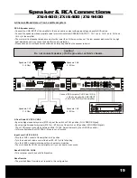
Page 15: ...rom e g the driver s seat Power LED If the green LED is illuminated the amp is in operation mode Protect LED If the red LED is illuminated a Overheated b Speaker wires shorted c Overload Impedance less Power Supply d Amplifier is damaged The built in electronic diagnostic protection saves the amplifier and speakers from serious damage If the red LED lights up due to overheating let the amplifier c...

Page 16: ... By using smaller speaker systems Ø 8 7cm Ø16cm set the switch on HP position HIGH PASS Signal The cut off frequency should be between 60Hz 150Hz Adjust the level by the LO PASS contoller In this configuration the LOW PASS Mode is out of function Input Level Turn the LEVEL control of the amplifier to 6V position Turn the head unit volume control to about 80 90 of its full setting Turn the LEVEL co...

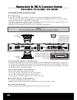
Page 17: ... regulates the Bass Level from f i the driver s seat Connect RCA outputs CH1 2 or SUB OUT of the head unit with LINE INPUT CH1 2 and CH3 4 of the amplifier Subwoofer 4 8 Ohm Bass Remote Control Connection for remote control This Contoller regulates the Bass Level from f i the driver s seat Speaker RCA Connections ZXi 4000 ZXi 6000 ZXi 9000 1 Channel Mode Mono Subwoofer bridged RCA Speaker wiring C...

Page 18: ...ed the amp is in operation mode Protect LED If the red LED is illuminated a Overheated b Speaker wires shorted c Overload Impedance less Power Supply d Amplifier is damaged The built in electronic diagnostic protection saves the amplifier and speakers from serious damage If the red LED lights up due to overheating let the amplifier cooled down a while and then turn it on again If the red light is ...

Page 19: ...t off frequency should be between 60Hz 150Hz Adjust the level by the LO PASS contoller In this configuration the LOW PASS Mode is out of function Input Level CH1 2 CH3 4 Turn the LEVEL control of the amplifier to 6V position Turn the head unit volume control to about 80 90 of its full setting Turn the LEVEL control clockwise until you hear some distortion Then turn back the LEVEL control slightly ...

Page 20: ...n Please use the Bass EQ carefully The additional boost may result in clipping or overload Bass Remote CH3 4 Subwoofer 2 The provided Bass Remote regulates the Bass Level of CH3 4 from e g the driver s seat Bass Remote Control Connection for remote control This Contoller regulates the Bass Level from f i the driver s seat Speaker RCA Connections ZXi 4400 ZXi 6400 ZXi 9400 3 Channel Mode 2 Mono Sub...

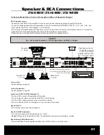
Page 21: ... Channel Mode Stereo Front or Rearsystem Mono Subwoofer bridged RCA Speaker wiring Connect the LINE INPUT of the amplifier to the head unit line output with appropriate good quality RCA cables Connect the speakers subwoofer with appropriate wires to the terminal block SPEAKER OUTPUT CH1 and CH2 and the subwoofer with CH3 4 Mono bridged of the amplifier The minimum final speaker subwoofer impedance...

Page 22: ...ound Rememaber to isolate the problem first unplug amplifier input RCAcables if the noise is still present check the speaker leads if not plug the RCA s back and investigate the source driving the amplifier one component at a time A ticking or whine that changes with engine RPM 1 This problem could be caused by radiation pickup of RCA cables too near to a fuel pump or a distributor for instance re...

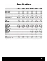
Page 23: ...0 dB 47 kOhm 265 x 64 0 2 6 Volt 1 x 60A 30Hz 150Hz 0 18 dB 10Hz 1200Hz 360 390 2 x 300 2 x 600 2 x 150 2 x 300 1 x 600 1 x 1200 yes Full range ZXi 9000 MkII 2 0 05 200 90 dB 60 dB 47 kOhm 265 x 64 0 2 6 Volt 2 x 50A 30Hz 150Hz 0 18 dB 10Hz 1200Hz 400 430 2 x 450 2 x 900 2 x 300 2 x 450 1 x 900 1 x 1800 yes Full range ZXi 4400 MkII 4 30Hz 150Hz 0 18 dB 10Hz 1200Hz 0 03 200 90 dB 60 dB 47 kOhm 30Hz...

Page 24: ...Distribution Audio Design GmbH Am Breilingsweg 3 76709 Kronau Germany Tel 49 0 7253 9465 0 Fax 9465 10 www audiodesign de ...

Reviews: