High-Flying
HF-LPT100 Low Power WiFi Module User Manual
Shanghai High-Flying Electronics Technology Co., Ltd(www.hi-flying.com)
- 17 -
Notes:
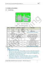
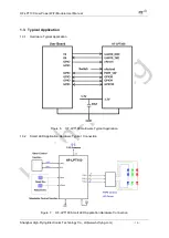
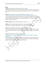
nReset-
Module hardware reset signal.
Input. Logics “0” effective.
There is pull-up resister internal and no external pull-up required. When module power up or some
issue happened, MCU need assert nRST signal “0” at least 10ms, then set” 1” to keep module fully
reset.
nReload
- Module restore to factory default configuration.
Input. Logics “0” effective.
(This pin is recommend to connect to button, is used to enter wireless upgrade mode)
User can de-assert nReload
signal “0” more than 3s through button or MCU pin, then release, module
will restore to factory default configuration and re-start boot up process.. If nReload function not
required, can leave this pin open.
UART0_TXD/RXD
- UART port data transmit and receive signal.
PWM-n-
PWM control signal output. It can also be configured as GPIO output.
“AT+LPTIO=on” command configure PWM_1 pin as nLink
、
PWM_2 pin as nReady
nReset-
Module hardware reset signal.
Input. Logics “0” effective.
There is pull-up resister internal and no external pull-up required. When module power up or some
issue happened, MCU need assert nRST signal “0” at least 10ms, then set” 1” to keep module fully
reset.
nLink-
Module WIFI connection status indication. Output.
(This pin is recommend to connect to LED, indicate status when the module in wireless
upgrade mode)
When module connects to AP (AP associated), this pin
will output “0”. This signal used to judge if
module already at WiFi connection status. Thers is pull-up resister internal and no external pull-up
required. If nLink function not required, can leave this pin open.


