


O P E R A T O R M A N U A L
- 8 -
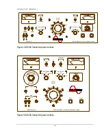
C O U P L E R M O D E
The COUPLER MODE switch is used to connect the internal radar coupler into the output circuit. The
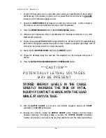
COUPLER MODE must be in either RADAR (thump voltages up to 25 kV) or DIRECT position or the high
voltage cannot be energized. If the switch is operated to another position when the high voltage is energized,
the output will turn off.
O U T P U T T A P
The OUTPUT TAP switch provides maximum output voltage selection while configuring the discharge
capacitor bank for the output voltage selected. The use of this switch provides a constant energy for capacitor
discharge even at lower output voltages. When in any one of the OFF positions, the high voltage cannot be
energized. If the switch is operated during testing, the output will de-energize. When changing tap positions
allow 20 seconds for the motorized switch to achieve final position.
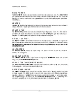
E X T I N T L K
The EXT INTLK external interlock socket provides a safety interlock to disable the high voltage control
circuits. A normally closed switch from a test cage or foot switch can be wired to this connector to provide
access control or electrical lockout ability. The circuit is within the 120Vac control circuit.
Note regarding the use of MC connectors:
The MC connector requires the operator to push IN before pulling OUT when disconnecting.


