background image

O P E R A T O R   M A N U A L  

- 9 - 

SETTING UP THE EQUIPMENT 

The setup of this equipment has been minimized by careful consideration for the operator during design. The 

CDS Series’ one-piece FIELD PORTABLE construction makes this the preferred unit for fault locating.   

1. 

Select a location

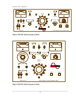
 for the unit that will allow easy viewing of the meters at a safe distance 

from the test cable. 

Caution!! 

Before making any cable connections, ensure that the cable being 

tested has been properly identified, de-energized, and grounded! 

2. 

Be sure that all the controls are off

,


in their de-energized or fully counterclockwise 

position. 

3. 

Unspool the cables onto the ground. 

Separate the input line cord,


ground lead and 

output cables from each other

.


4. 

Secure the ground test lead to the cabinet.


The


Ground


stud on the rear panel of the 

unit must be used for that purpose. A 4 AWG braided copper lead has been provided for the 
ground connection. Proper grounds are essential when fault locating with a capacitor 

discharge device. Connect the ground lead cable clamp to the station ground of the cable 
being tested. 


SECTION 

Summary of Contents for CDS Series

Page 1: ...uctions for the operation of a High Voltage power source The operator of this equipment must use good judgement and follow all safety precautions noted in this guide to ensure the protection of himself and others in close proximity to the test area Failure to follow the instructions could result in injury or death Proper grounding of the test set must be done prior to connecting this unit to a pow...

Page 2: ...OperatorManual HIGH VOLTAGE INC 31 County Route 7A Copake N Y 12516 Phone 518 329 3275 Fax 518 329 3271 http www hvinc com ...

Page 3: ...eration 2 Features and Specifications 3 4 Controls and Indicators 6 7 S E C T I O N 2 Setting up the Equipment 8 Operating the Equipment 9 17 Hipot Burn Mode 9 11 Capacitor Discharge Fault Locating Thumping 12 14 Capacitor Discharge Fault Locating TDR 15 17 Blank Page for Notes 18 S E C T I O N 3 Performing Special Operations 19 Miscellaneous 19 Return Material 20 Warranty 21 22 ...

Page 4: ...cedures for the use of this type of equipment This Operator Manual is organized to provide information on the CDS Series in steps that familiarize the new operator with the entire scope of operation of this test set Section 1 Specifications and Controls Section 2 Setup and Operation Section 3 Performing Special Operations TheFunctions Features andSpecifications oftheCDSSeriesofCapacitorDischarge H...

Page 5: ...eration With the use of buried underground cables in primary feed electrical installations it is necessary to locate faults and repair the cable the cable as quickly as possible to restore power to affected areas The CDS Series of Capacitor Discharge Hipot Cable Fault Locators uses an energy storage capacitor to provide a pulse of energy to create an audible sound at the fault location for tracing...

Page 6: ...ot Fault Locator Continuously adjustable output voltage Zero Start Interlock provision Single range volt meter Single range current meter Single cycle or continuous Capacitor Discharge operation Adjustable discharge timing 3 9 seconds Motorized Output Voltage Tap Switch Manually operated Coupler Switch with Radar and Direct position Two internal discharge solenoids one for the output cable one for...

Page 7: ...O P E R A T O R M A N U A L 4 OPTIONS AVAILABLE Storage Reel system available for Output and Ground Cables CDS 36 available with 3 2kJ discharge capacitor ...

Page 8: ...O P E R A T O R M A N U A L 5 CDS MODEL SPECIFICATIONS See last page of parts list for Specifications ...

Page 9: ...8kV OFF OFF 9kV 36kV INTLK EXT DISCHARGE TIMING 3 SEC 9 SEC Figure 1 CDS36U Series front panel controls G S R E M E ENC Y T OP HEATER MAIN POWER MODEL CDS 2010 DISCHARGE MODE MODE OPERATING SINGLE PULSE HIPOT BURN CONTINUOUS CAP DISCHARGE OUTPUT ADJUST STOP START CONSTANT ENERGY CAPACITOR DISCHARGE SYSTEM 50 40 60 70 80 90 100 30 20 10 0 ON OFF INTLK EXT DIRECT COUPLER MODE RADAR OFF 10kV OUTPUT T...

Page 10: ...igh setting The control must be at ZERO 0 to energize the high voltage circuits The output control must always be returned to zero at the completion of testing prior to de energizing the output V O L T M E T E R The KILOVOLT METER indicates the output voltage 1 precision resistors minimize the need for re calibration due to aging shift C U R R E N T M E T E R The CURRENT METER provides output curr...

Page 11: ...ovides a constant energy for capacitor discharge even at lower output voltages When in any one of the OFF positions the high voltage cannot be energized If the switch is operated during testing the output will de energize When changing tap positions allow 20 seconds for the motorized switch to achieve final position E X T I N T L K The EXT INTLK external interlock socket provides a safety interloc...

Page 12: ...ing tested has been properly identified de energized and grounded 2 Be sure that all the controls are off in their de energized or fully counterclockwise position 3 Unspool the cables onto the ground Separate the input line cord ground lead and output cables from each other 4 Secure the ground test lead to the cabinet TheGroundstud on the rear panel of the unit must be used for that purpose A 4 AW...

Page 13: ... any cable connections ensure that the cable being tested has been properly identified de energized and grounded 2 Make sure that all insulators stress cones and pot heads are clean and free of moisture This will prevent flashover and minimize leakage The shields of all cables must be securely tied to ground at the nearest end of the cable 3 Isolate the far end of the conductors under test for the...

Page 14: ...UT TAP 9 18 36 kVdc 5 10 20 kVdc for the cable being tested When changing tap positions the switch must be in position to energize high voltage allow 20 seconds for the motorized switch to achieve final position 12 Be sure to place the COUPLER MODE switch in the DIRECT position C A U T I O N P O T E N T I A L LY L E T H A L V O LTA G E S M AY B E P R E S E N T 13 With the OUTPUT ADJUST at zero zer...

Page 15: ...t or operation the depress the STOP pushbutton the output cable load will be discharged through an internal discharge resistor Turn off the MAIN POWER circuit breaker 18 Always use a GROUND HOOK to ground the cable s prior to disconnecting the output cable ...

Page 16: ... other than the fault site The shields of all cables must be securely tied to ground at the nearest end of the cable 3 Isolate the far end of the conductors under test for the test voltage that may mean separating some of the conductors in a multi conductor cable from each other and their shields 4 Any conductors or wires in the cable or the vicinity not being tested must be grounded to avoid a bu...

Page 17: ...ons the switch must be in position to energize high voltage allow 20 seconds for the motorized switch to achieve final position 12 Assure that the COUPLER MODE switch is in the DIRECT position 13 Choose the discharge timing 3 9 seconds This adjustment can be re adjusted during test if desired 14 Place the CAPACITOR DISCHARGE MODE in CONTINUOUS position C A U T I O N P O T E N T I A L LY L E T H A ...

Page 18: ...t depress the STOP pushbutton to interrupt the test cycling 18 At completion of test or operation the depress the STOP pushbutton the internal capacitor s and output cable load will be discharged through two internal discharge resistors Turn off the MAIN POWER circuit breaker 19 Always use a GROUND HOOK to ground the cable s prior to disconnecting the output cable ...

Page 19: ...connector on the control panel marked TDR SIGNAL The TDR trigger input if on TDR connects to the BNC marked TDR TRIGGER 3 Operate the COUPLER switch to the RADAR position Caution Before making any cable connections ensure that the cable being tested has been properly identified de energized and grounded 4 Make sure that all insulators stress cones and pot heads are clean and free of moisture This ...

Page 20: ...to achieve final position 13 Place the OPERATING MODE switch in the CAP DISCHARGE position 14 Make sure the DISCHARGE MODE switch is in the center position 15 Set up the TDR in accordance with manufacturer s instructions At this time you should see a low voltage trace on the screen and the TDR should be armed 16 With the OUTPUT ADJUST at zero zero start interlock engaged depress the START pushbutt...

Page 21: ...O P E R A T O R M A N U A L 18 21 Always use a GROUND HOOK to ground the cable s prior to disconnecting the output cable ...

Page 22: ...O P E R A T O R M A N U A L 19 THIS PAGE LEFT BLANK FOR APPLICATION NOTES ...

Page 23: ...rature If the current meter will not calibrate the meter should be replaced once it has been determined the current sense resistor is not the cause The certification of meters on a yearly basis is recommended to ensure accurate test results Miscellaneous Oil Insulated High Voltage Tanks Although not suggested for units in Warranty the oil filled tanks in all the DTS SERIES Capacitor Discharge Hipo...

Page 24: ... if the return of the equipment is appropriate If deemed appropriate a Return Authorization Number will be issued At that time the Purchaser will be instructed how to mark and return the equipment The above procedure must be adhered to in order to ensure prompt service No equipment should be returned without the prior knowledge and authorization of High Voltage Inc REPLACEMENT PARTS ORDERING To or...

Page 25: ...red by the purchaser for labor and or materials incidental to the inspection repair replacement or issuance of credit for product or materials under warranty is the sole responsibility of the purchaser This warranty applies solely to products manufactured by High Voltage It does not apply to parts accessories or materials not manufactured by High Voltage or to consumables If purchaser s claim rela...

Page 26: ...lusively determined by High Voltage and any determination shall be final and binding THIS WARRANTY IS EXPRESSLY IN LIEU OF ALL OTHER WARRANTIES EXPRESSED OR IMPLIED ON THE PART OF HIGH VOLTAGE INCLUDING THE WARRANTIES OF MERCHANTABILITY FITNESS FOR A PARTICULAR USE AND NON INFRINGEMENT ARISING FROM ANY BREACH THEREOF AND HIGH VOLTAGE NEITHER ASSUMES NOR AUTHORIZES ANY OTHER PERSON FIRM OR CORPORAT...

Page 27: ...Y OUTPUT 115V 3A SINGLE RECEPT WHT HERRINGTON 3456735 1 07 483 CONNECTOR FLIP COVER HERRINGTON 357346 J2 1 07 440 CONNECTOR BULKHEAD 2 SOCKET CINCH S302AB J3 5 3 07 206 CONNECTOR COAXIAL BNC AMPHENOL UG1094 A U K1 1 11 150 CONTACTOR 3PDT 15A 120 Vac COIL MAGNECRAFT W389ACX 14 L1 1 T063 REACTOR CURRENT LIMITING HVI 063 GAP 220 M1 1 13 079 METER ANALOG 100 µA MOVEMENT SCALED 0 20 dc KILOVOLTS M2 1 1...

Page 28: ...1 10 226 SWITCH CONTACT BLOCK NC NC EAO 704 910 4 NEWARK 50F7321 SOL1 1 83 538 SOLENOID ASSEMBLY N O N C FORM C 45kVdc HVI HVS 0021A SOL2 3 2 83 541 SOLENOID ASSEMBLY N O HIGH CURRENT 45kVdc HVI HVS 0184A SOL4 5 2 83 543 SOLENOID ASSEMBLY N O 50kVdc HVI HVS 0204A SOL6 1 83 552 SOLENOID ASSEMBLY N O PULSE CURRENT 40kVdc HVI HVS 0215A SG1 1 06 205 SPARKGAP 90V CP CLARE CG90l T1 1 25 108 TRANSFORMER ...

Page 29: ...ANSFORMER PULSE TRIGGER 213T 26 AWG WIRE 1 27 238 RING CORE PHILIPS 500XT400 3C85 A6 A1 82 533 TDR PROTECTION PCB HVI PCB 019 D1 2 2 06 217 TRANSIENT VOLTAGE SUPPRESSORS 51V 1 5KE51A MOUSER 610 1 5CE51A D3 4 2 04 017 DIODE ZENER 10V 5W 1N5347B J1 1 07 130 CONNECTOR HEADER 5 PIN 1 SPACING MOLEX 22 23 2051 MOV1 1 06 210 METAL OXIDE VARISTOR 250 V V250LA20A P1 1 07 114 CONNECTOR CABLE 5 PIN 1 SPACING...

Page 30: ...ED EPR X RAY CABLE ASSEMBLY HV CDS 0157A 1 88 328 50FT GROUND CABLE ASSEMBLY HV CDS 0180A 1 SCHEMATIC WIRING HV CDS 0072S REV I 12ft 22 508 INPUT POWER CABLE 12 3 1 07 488 CONN PLUG 125V 20A 1 34 145 PANEL CONTROL HV CDS 0061D 1 88 050 VISE GRIP WITH MC CONNECTOR ASSEMBLY HV ACC 1046A 2 07 471 STRAIN RELIEF PLASTIC NEWARK 91F2302 1 07 490 CONNECTOR CABLE PLUG MULTI CONTACT KST14AR N 120 CABLE REEL...

Page 31: ...t 1000 joules at full All Output Taps 80µF 5kV 20µF 10kV 5µF 20kV Polarity Negative standard Bipolar available with alternating Positive and Negative output in Thumper Mode Duty Continuous Kilovoltmeter 0 20 kVdc 2 F S Current Meter 0 400 mAdc 2 Full Scale Terminations Input line 10 Ft Return High Voltage Cable 50 ft or 12 ft for use with cable reel 2 AWG Braided Ground Lead 50 ft or 12 ft for use...

Page 32: ...AUXILLARY OUTPUT 115V 3A SINGLE RECEPT WHT HERRINGTON 3456735 1 07 483 CONNECTOR FLIP COVER HERRINGTON 357346 J2 1 07 440 CONNECTOR BULKHEAD 2 SOCKET CINCH S302AB J3 4 2 07 206 CONNECTOR COAXIAL BNC AMPHENOL UG1094 A U K1 1 11 150 CONTACTOR 3PDT 15A 120 Vac COIL MAGNECRAFT W389ACX 14 L1 1 T063 REACTOR CURRENT LIMITING HVI 063 GAP 220 M1 1 13 079 METER ANALOG 100 µA MOVEMENT SCALED 0 20 dc KILOVOLT...

Page 33: ...O 704 074 2 NEWARK 50F7339 1 10 226 SWITCH CONTACT BLOCK NC NC EAO 704 910 4 NEWARK 50F7321 SOL1 1 83 538 SOLENOID ASSEMBLY N O N C FORM C 45kVdc HVI HVS 0021A SOL2 3 2 83 537 SOLENOID ASSEMBLY N O HIGH CURRENT 45kVdc HVI HVS 0232A SOL4 5 2 83 543 SOLENOID ASSEMBLY N O 50kVdc HVI HVS 0204A SOL6 1 83 552 SOLENOID ASSEMBLY N O PULSE CURRENT 40kVdc HVI HVS 0215A T1 1 25 108 TRANSFORMER VARIABLE 120V ...

Page 34: ...12 201 SOLENOID PULL TYPE 24Vdc GUARDIAN 11HD C 24VDC T1 1 T147 TRANSFORMER HIGH VOLTAGE STEP UP HVI 147 A5 HIGH VOLTAGE CAPACITOR ASSEMBLY C1 1 03 205 CAPACITOR HV 4 X 20µF 5kVdc CONDENSER PRODUCTS NOC4X5M20K R1 8 8 01 378 RESISTOR METAL FILM 12 5W 2 5M 10 EBG SSP52 2 5M A6 TDR COUPLER ASSEMBLY C1 3 03 225 CAPACITOR CERAMIC DOORKNOB CERA MITE 40DKD33 NEWARK 46F5302 R1 2 01 608 RESISTOR WIREWOUND ...

Page 35: ... 120 CONNECTOR CABLE 8 PIN 1 SPACING MOLEX 22 01 2087 8 07 104 CONNECTOR PINS 1 SPACING MOLEX 08 50 0114 PCB 1 14 001 PRINTED CIRCUIT BOARD HVI PCB 001 R1 1 01 412 RESISTOR WIREWOUND 11W 25Ω 1 R2 1 01 150 RESISTOR METAL FILM 0 25W 100K 1 RY1 1 11 110 RELAY PCB MOUNT SPDT 24 Vdc COIL P B T70L5D131 24 SG1 1 06 205 SPARK GAP 90V CP CLARE CG90L MISC 2 23 119 KNOB SKIRTED POINTER ALCO PKD 70B 1 4 50ft ...

Page 36: ... Capacitor Discharge Energy µF kV tap 250 Joules at half output 1000 joules at full All Output Taps 80µF 5kV 20µF 10kV 5µF 20kV Polarity Negative Duty Continuous Kilovoltmeter 0 20 kVdc 2 F S Current Meter 0 400 mAdc 2 Full Scale Terminations Input line 10 Ft Return High Voltage Cable 50 ft or 6 ft for use with cable reel 4 AWG Braided Ground Lead 25 ft Size 27w x 27d x 48 high 69CM x 69CM x 122CM...

Page 37: ......

Page 38: ......

Page 39: ......

Page 40: ......

Page 41: ......

Reviews: