


O P E R A T O R M A N U A L
- 10 -
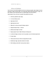
Operating the Equipment
This section provides step-by-step instruction on various test methods. Many facilities have their own
in-house test procedures, and this manual is not to supercede these. The purpose of this section is
to explain the capabilities of this test set in real-world applications.
DC Insulation Testing of Cables in the Hipot/Burn Mode
When testing cables, either single or three phase, there are certain steps that must be observed to ensure
safe operation.
1.
Ensure that all the steps listed in Setting up the Equipment
have been accomplished.
Take special note to ground the unit to a solid earth ground using the supplied 4 AWG
braided copper lead. Connect the ground lead cable clamp to the station ground of the
cable being tested.
Caution!!!
Before making any cable connections, ensure that the cable being
tested has been properly identified, de-energized, and grounded!
2.
Make sure that all insulators, stress cones, and pot heads are clean and free of moisture.
This will prevent flashover and minimize leakage.
The shields of all cables must be securely tied to ground at the
nearest end of the cable.
3.
Isolate the far end of the conductors under test for the test voltage; that may mean
separating some of the conductors in a multi-conductor cable from each other and their
shields.
4.
Any conductors or wires in the cable or the vicinity not being tested must be grounded to
avoid a buildup of charge and possible shock hazard.
5.
Connect the RETURN clamp to the neutral or shield of the cable being tested.
6.
Connect the HV lead clamp to the center conductor of the cable being tested.
Note: If an output cable reel is being used, connect the high voltage MC connector to the
center plug on the reel. The MC connector requires the operator to push IN before pulling


