


O P E R A T O R M A N U A L
- 16 -
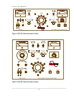
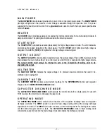
Capacitor Discharge Fault Locating
High Voltage Cables Using a TDR Device
When testing cables, either single or three phase, there are certain steps that must be observed to ensure
safe operation.
Please Note: The TDR Coupler is always active. When in the DIRECT MODE, the TDR can
operate as a TDR-RADAR, but the Arc-Reflection Mode of the TDR will not work in DIRECT.
1.
Ensure that all the steps listed in
Setting up the Equipment
have been accomplished.
Take special note to ground the unit to a solid earth ground using the supplied 4 AWG braided copper
lead. Connect the ground lead cable clamp to the station ground of the cable being tested.
2.
The TDR or Radar device should be plugged directly into the AC receptacle on the side panel of
the CDS cabinet. The TDR signal input is connected to the BNC connector (on the control panel) marked
TDR SIGNAL. The TDR trigger input (if on TDR) connects to the BNC marked TDR TRIGGER.
3. Operate
the
COUPLER switch to the RADAR position.
Caution!!!
Before making any cable connections, ensure that the cable being
tested has been properly identified, de-energized, and grounded!
4.
Make sure that all insulators, stress cones, and pot heads are clean and free of moisture. This
will prevent flashover in areas other than the fault site.
The shields of all cables must be securely tied to ground at the
nearest end of the cable.
5.
Isolate the far end of the conductors under test for the test voltage; that may mean separating
some of the conductors in a multi-conductor cable from each other and their shields.
6.
Any conductors or wires in the cable or the vicinity not being tested must be grounded to avoid a
buildup of charge and possible shock hazard.
7.
Connect the RETURN clamp to the neutral or shield of the cable being tested.
8.
Connect the HV lead clamp to the center conductor of the cable being tested.


