O P E R A T O R M A N U A L
17
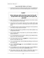
Using the BURN MODE on AC Cables
1.
Ensure that all the steps listed in Setting up the Equipment have been accomplished. Take
special note to ground the power section and the high voltage tank to a solid earth ground.
Caution!!
Before making any cable connections, ensure that the cable
being tested has been properly identified, de-energized, and
grounded!
2.
Make sure that all insulators, stress cones, and pot heads are clean and free of moisture.
This will prevent flashover and minimize leakage.
3.
Isolate the far end of the conductors under test for the test voltage; that may mean
separating some of the conductors in a multi-conductor cable from each other and their
shields.
4.
Any conductors or wires in the cable or the vicinity not being tested must be grounded to
avoid a buildup of charge and possible shock hazard.
5.
Voltage must be applied according to specifications from the cable manufacturer or any
other applicable test standards
6.
Prior to connecting anything to the test sample, be sure the test sample is identified, de-
energized and grounded.
7.
First, the cable capacitance must be measured to determine the best operating frequency.
Place the control near the cable being tested.
8.
Connect the input power terminal block to a grounded 220 v (+/-10%), 50/60 Hz source. A
generator is an acceptable power source.
9.
Turn on the main circuit breaker. The MAIN POWER light will illuminate at both the power
section and the control.
10.
Operate the METER MODE to
µ
F position. Adjust the CAP ZERO for full scale deflection
(ZERO) on the meter.
11.
Connect the HOT post to the center conductor of the test cable. Connect the COM post to
the grounded shield of the test cable. Read the CAPACITANCE scale(x10).
12.
If the reading is below 6.0
µ
F (about 6 divisions on x10 multiplier) depress the x1
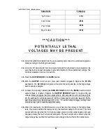
pushbutton. Then following table provides operating frequency versus capacitance.


