background image


Chapter 4 Advance Settings                                                                                                                Page 45 

Port Forwarding 

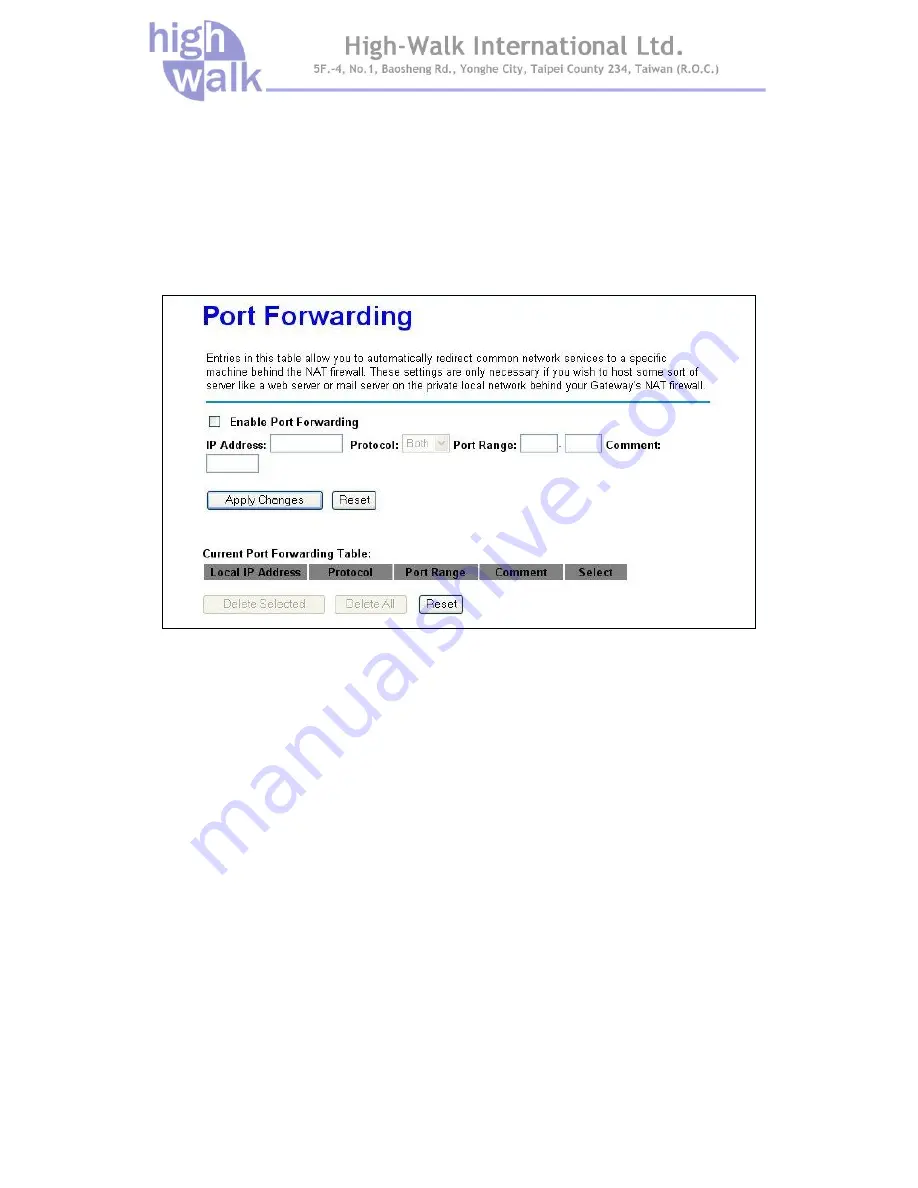
Entries in this table allow you to automatically redirect common network services to a specific 

machine behind the NAT firewall. These settings are only necessary if you wish to host some sort of 

server like a web server or mail server on the private local network behind your Gateway's NAT 

firewall.   


Figure 38 Port Forwarding Settings 

Select 

Enable Port Forwarding

 to activate this setting. Clear this check box to disable it. 

Select 

Protocol

 from the drop-down list box. You can assign the filter protocol to TCP, UDP or both. 

After that you may enter a range of port numbers to be forwarded, and the local IP address of the 

desired server. Click 

Apply Changes

 to save the settings. Click 

Reset

 to start configuring this part 

of the screen again. 

Summary of Contents for HWW-3050

Page 1: ...0 02 2 1 11 1n n D Dr ra af ft t 2 2 0 0 2 2 4 4G GH Hz z W Wi ir re el le es ss s B Br ro oa ad db ba an nd d R Ro ou ut te er r M Mo od de el l H HW WW W 3 30 05 50 0 User s Manual Version 1 0 Date of Issue May 2009 ...

Page 2: ...nded to guide professional installer to install the Wireless Broadband Router and how to build the infrastructure centered on it It includes procedures to assist you in avoiding unforeseen problems Conventions For your attention on important parts special characters and patterns are used in this manual This indicates a warning or caution that you have to abide This indicates an important note that...

Page 3: ... reception which can be determined by turning the equipment off and on the user is encouraged to try to correct the interference by one of the following measures Reorient or relocate the receiving antenna Increase the separation between the equipment and receiver Connect the equipment into an outlet on a circuit different from that to which the receiver is connected Consult the dealer or an experi...

Page 4: ...a distance of at least 100cm between you and the antenna of the installed equipment This transmitter must not be co located or operating in conjunction with any other antenna or transmitter The availability of some specific channels and or operational frequency bands are country dependent and are firmware programmed at the factory to match the intended destination The firmware setting is not acces...

Page 5: ... Chapter 2 Hardware Installation 4 Product Package 4 System Requirements 4 Mechanical Description 5 Chapter 3 Setup Wizard 7 How to Access the Web based Configuration Utility 7 Setup Wizard 8 Chapter 4 Advance Settings 12 Operation Mode 12 Wireless Settings 13 Basic 13 AP Mode 13 Client Mode 16 WDS 17 AP WDS 18 Advance 19 Security 21 WEP 22 WPA WPA2 23 Access Control 25 WDS Setting 26 Site Survey ...

Page 6: ...ering 46 DMZ 46 QoS 48 Chapter 5 Management 49 Status 49 Statistics 50 DDNS 50 Time Zone Setting 51 Denial of Service 52 Log 53 Upgrade Firmware 53 Save Load Setting 54 Password 55 Chapter 6 Universal Repeater and WISP Concept 56 Universal Repeater 56 How to Configure Universal Repeater Mode 56 WISP Mode 58 How to Configure WISP Mode 59 Chapter 7 Limited Warranty 61 ...

Page 7: ...gs 11 Figure 11 Operation Mode Settings 12 Figure 12 Wireless Basic Settings 13 Figure 13 Client Mode Settings 16 Figure 14 WDS Settings 17 Figure 15 AP WDS Settings 18 Figure 16 Wireless Advance Settings 19 Figure 17 Wireless Security Settings 21 Figure 18 WEP Encryption 22 Figure 19 WPA Settings 23 Figure 20 WPA2 Settings 23 Figure 21 WPA Mixed Settings 24 Figure 22 Access Control Settings 25 Fi...

Page 8: ...re 41 Status Page 49 Figure 42 Statistics Page 50 Figure 43 DDNS Settings 50 Figure 44 Time Zone Settings 51 Figure 45 Denial of Service Settings 52 Figure 46 System Log Page 53 Figure 47 Upgrade Firmware 53 Figure 48 Save Reload Settings 54 Figure 49 Password Settings 55 Figure 50 Universal Repeater Application 56 Figure 51 Universal Repeater Configure Progress 57 Figure 52 WISP Application 58 Fi...

Page 9: ...TABLE Table 1 LED Description Table 5 Table 2 The Wireless Broadband Router Port Description Table 6 ...

Page 10: ...nd is easy to configure and operate even for non technical users Instructions for installing and configuring the Wireless Router can be found in this manual Before you install and use this product please read this manual carefully to ensure that you take full advantage of its functionality Key Feature and Benefits Ultimate Performance Cost effective Firewall Router Security Setup Wi Fi Protection ...

Page 11: ...eless Infrastructure with Stations Attaching to a Wired LAN The IEEE 802 11n Draft 2 0 2 4GHz Wireless Broadband Router will provide access to your local LAN An integrated wireless and wired LAN is called an Infrastructure configuration A group of wireless LAN PC users and an Access Point construct a Basic Service Set BSS Each wireless PC in this BSS can talk to any computer on your network via th...

Page 12: ...f any of the above items is not included or damaged please contact your local dealer for support System Requirements Installation of HWW 3050 IEEE 802 11n Draft 2 0 2 4GHz Wireless Router requires 1 An AC power outlet 100 240V 50 60Hz which supplies the power for the Access Point Please use the power adapter that contain in the package not to change to use the one that make up by non original fact...

Page 13: ... An active device is connected to the 10 100MB WAN port WAN Green Blinking The WAN port is sending or receiving data WLAN Green Blinking Sending or receiving data via wireless link On An active device is connected to the corresponding 10 100MB LAN port LAN 1 4 Green Blinking The corresponding LAN port is sending or receiving data WPS LED Green Wi Fi Protected Setup compliant Push WPS button for 3 ...

Page 14: ...set LED start blinking Then release the button and the Wireless Broadband Router will reboot ANT 1 2 Combine the antenna with the Router to wirelessly connect to the 802 11b g n networks Note The antenna can rotate around 180 only not up to 360 PWR Power socket DC 12V 1 0A minimum WAN The port for connecting your ADSL or cable modem LAN 1 4 4 switch ports for your networked computers and or other ...

Page 15: ... wired connection Please set a fixed IP address within the range of 192 168 1 X X can t be 254 to your computer If you attempt to use a wireless connection you must also set a configuration in your computer in advance as below SSID Wireless WEP disable Channel 1 Activate your web browser and type in the IP address of your Wireless Router in the Address or location field and press Enter The default...

Page 16: ...to return to the last screen Next Click Next to continue to the next screen The setup wizard consists of a series of screens to help you configure router No configuration settings will be saved to the Wireless Broadband Router until you go through the entire setup process and click Finished Step1 Configure the Operation Mode to let the device to as a Gateway or Bridge or Wireless ISP and click Nex...

Page 17: ...r geographical location if need and click Next Figure 6 Step2 Time Zone Settings Step3 Configure the LAN interface you may change the IP address and Subnet Mask of the device and click Next or if not to change the IP address and Subnet Mask click Next to the next step The default IP Address is http 192 168 1 254 Figure 7 Step3 LAN Interface Settings ...

Page 18: ... Step4 Configure the WAN interface you may configure the WAN Access Type as Static IP DHCP Client PPPoE PPTP and L2TP according to the WAN access type of your ISP that you connect and click Next Figure 8 Step4 WAN Interface Settings ...

Page 19: ...ode Network Type SSID Channel Width Control Sideband and Channel Number and click Next Figure 9 Step5 Wireless Basic Settings Step6 Configure Wireless Security you may configure the wireless security setting to WEP WPA TKIP WPA2 AES or WPA2 Mixed and click Finish to complete the setup wizard Figure 10 Step6 Wireless Security Settings ...

Page 20: ...figuration It always connects internet via ADSL Cable Modem LAN interface WAN interface Wireless interface NAT and Firewall modules are applied to this mode Bridge This mode all interface LAN WAN and Wireless regards as bridge NAT Firewall and all routers functions are not supported Wireless ISP This mode switch Wireless interface to WAN port and all Ethernet ports are in bridge mode Wireless inte...

Page 21: ...allow you to set the following configuration items AP Mode You can configure the Wireless Broadband Router to AP Mode to be an Access Point of the real world When set to AP Mode you can configure the SSID Channel Number Broadcast SSID and Multiple AP Figure 12 Wireless Basic Settings Disable Wireless LAN Interface Select this check box to disable the wireless Radio Band ...

Page 22: ...d the Channel Number will be 1 11 1 13 for ETSI domain When Channel Width is 40MHz you can configure the Control Sideband to Upper or Lower If Control Sideband is Upper the Channel Number will be 5 11 5 13 for ETSI domain if Control Sideband is Lower the Channel Number will be 1 9 Channel Number The permissible radio channels range from channel 1 to 11 1 13 for ETSI domain default is 11 depending ...

Page 23: ... Press Show Active Clients button to display the associated client list Enable Universal Repeater Mode Acting as AP and client simultaneously Select the check box to enable Universal Repeater function More setting and application for Universal Repeater refer to Chapter 6 SSID of Extended Interface Input the SSID of the Access Point that the Wireless Broadband Router wants to associate when Univers...

Page 24: ... Mode Settings Enable Mac Clone Single Ethernet Client Select the check box to enable this function when set to Client Mode The wireless router will clone the MAC address of the computer to be the Ethernet MAC of the Wireless Broadband Router Enable Universal Repeater Mode Acting as AP and client simultaneously SSID of Extended Interface Select the check box to enable Universal Repeater feature an...

Page 25: ...onfigure the device to WDS Mode to be a wireless bridge and establish a wireless link with other Access Points When set the mode to WDS you can configure the Channel Width Channel Number and to enable Broadcast SSID or disable Figure 14 WDS Settings ...

Page 26: ...WDS You can configure the device to AP WDS Mode to be a wireless bridge and Access Points When set the mode to AP WDS you can configure the SSID Channel Width Channel Number and to enable Broadcast SSID or disable Figure 15 AP WDS Settings ...

Page 27: ...e This specifies the maximum size a data packet will be before splitting and creating a new packet The setting range is 256 2346 For example If you set value as 256 it means the packet will be fragmented into 256 bytes while transmitting RTS Threshold RTS Threshold is a mechanism implemented to prevent the Hidden Node problem If the size of the packet transmitted is larger than the value you set t...

Page 28: ...cess Points and between the IAPP and high layer management entities to support roaming The IAPP protocol uses TCP for inter Access Point communication and UDP for RADIUS request response exchanges It also uses Layer 2 frames to update the forwarding tables of Layer 2 devices Select Enable to turn on this feature Protection Select Enable to turn on this function Aggregation Select Enable to turn on...

Page 29: ...tion between wireless stations Access Points and your wired network Select the SSID that you want to enable the wireless security and configure the encryption settings Figure 17 Wireless Security Settings Encryption You may select encryption type to WEP WPA WPA2 and WPA Mixed from the drop down list ...

Page 30: ...ially for distributing encryption keys in a wireless network The Access Point supports IEEE 802 1x for keeping out unauthorized users and for verifying the credentials of users with RADIUS so that authorized users can access the network and services To use IEEE 802 1x you will need at least one common Extensible Authentication Protocol EAP method on your authentication server APs authenticator and...

Page 31: ...adecimal digits between 0 9 a f and A F 128 bits WEP Enter 13 ASCII characters or 26 hexadecimal digits between 0 9 a f and A F The WEP key must be set up exactly the same on the Wireless Broadband Router as they are on the wireless clients If you set 0011223344 for the Wireless Access Point the same WEP key 0011223344 must be assigned to other client stations WPA WPA2 The IEEE 802 11n Draft 2 0 2...

Page 32: ...only If encryption is WPA2 then the WPA2 cipher default value is AES only If encryption is WPA Mixed then the WPA cipher default value is TKIP and WPA2 cipher default value is AES Pre Shared Key Format The item provides two options for choice Passphrase and Hex 64 characters If select Passphrase type the pre shared key from 8 to 63 ASCII characters otherwise type the key from 8 to 64 Hex character...

Page 33: ...ons to access wireless network Input the MAC Address Comment and press Apply Changes to add the allow rule into the Current Access Control List Otherwise select Deny Listed to deny the wireless stations to access wireless network Input the MAC Address Comment and press Apply Changes to add the deny rule into the Current Access Control List The default of Wireless Access Control is disable Figure 2...

Page 34: ...Under WDS your Access Points are still functioning as a regular Access Point which can provide the link services to wireless clients If Wireless mode set to AP Mode or Client Mode then WDS function doesn t support Figure 23 WDS Settings Enable WDS check box and enter the MAC address of another AP you wirelessly want to connect to into the appropriate field either by clicking Apply Changes The impl...

Page 35: ...esses Connect button to associate the Access Point Press the Refresh button to flash Access Point list and select the AP to connect Figure 25 Wireless Site Survey WPS The WPS Wi Fi Protected Setup feature is defined by Wi Fi Alliance and the primary goal is to simplify the security setup and management of Wi Fi networks The router supports three types of WPS configuration mode including Client PIN...

Page 36: ...ogress When use Self PIN Number input that Self PIN Number that generate by the Wireless Broadband Router to wireless station utility and start to WPS progress When use Push Button press Start PBC to start Push Button mode WPS or just push the WPS button on the Wireless Router side When the wireless mode set to WDS this function will be disabled Figure 26 WPS Setting AP Mode Figure 27 WPS Setting ...

Page 37: ...ireless Broadband Router provides to setup wireless schedule rule function select the Enable Wireless Schedule check box to start this feature Before enable this feature remember to configure the system time first Figure 28 Wireless Schedule Settings ...

Page 38: ...allows you to manage the IP and DHCP Server setting for the wireless router Figure 29 LAN Interface Settings IP Address Subnet Mask Default Gateway Input the IP Address Subnet Mask and Default Gateway of the Wireless Broadband Router DHCP If you plan to use any external DHCP server select Disable Otherwise set the LAN address to Static and select Server If you set the DHCP server and configure you...

Page 39: ...s from the DHCP server Select Enable to turn on this function and press Set Static DHCP button to edit Domain Name Select the DHCP Server and set the Domain Name configure Clients as automatic IP allocation mode the Connection specific DNS Suffix will display the Domain Name on Clients 802 1d Spanning Tree Enable the 802 1d Spanning Tree and then the broadcast storm will be prevented Clone MAC Add...

Page 40: ...ess Subnet Mask Default Gateway Input a fix IP Address Subnet Mask and Default Gateway that provide by your ISP MTU Size Change the MTU size that your ISP provided The default value is 1500 and range is 1400 to 1500 bytes DNS1 2 3 Enter Domain Name Server IP address that your ISP provided Clone MAC Address Input the MAC Address that wants to be cloned Enable uPNP ...

Page 41: ...WAN ICMP response Enable Web Server Access on WAN You can select it when you want to configure the Wireless Broadband Router from the WAN interface Enable IPsec PPTP L2TP pass through on VPN connection You can select the VPN protocol according your request DHCP Client This setting is default value Host Name is optional It required by some ISPs for example at home Figure 31 DHCP Client Settings ...

Page 42: ...and input at most three DNS servers in the below field DNS 1 2 3 Enter Domain Name Server IP address that your ISP provided Clone MAC Address Input the MAC Address that wants to be cloned Enable uPNP You can select it according to your request Enable IGMP Proxy You can select it according to your request Enable Ping Access on WAN You can select it to enable WAN ICMP response Enable Web Server Acce...

Page 43: ...nd idle time Figure 32 PPPoE Settings User Name and Password The account and password are that your ISP assigned to you For security this field appears blank If you don t want to change the password leave it empty Service Name This field is optional Input the service name if your ISP requires it Otherwise leave it blank Connection Type ...

Page 44: ...e You may enter the number of time when connection type set to Connect on Demand MTU Size Change the MTU size that your ISP provided The default value is 1452 and range is 1360 to 1492 bytes Attain DNS Automatically You can select this option to get DNS address from the DHCP server Set DNS Manually You can select Set DNS Manually and input at most three DNS servers in the below field DNS 1 2 3 Ent...

Page 45: ...el with remote site directly to secure the data transmission among the connection User can use embedded PPTP client supported by this Wireless Broadband Router to make a VPN connection Figure 33 PPTP Settings IP Address and Subnet Mask Input the private IP address and subnet mask that your ISP assigned to you ...

Page 46: ... type means to setup the connection through the PPTP protocol by clicking the Connect button manually and clicking the Disconnect button manually Idle Time You may enter the number of time when connection type set to Connect on Demand MTU Size Change the MTU size that your ISP provided The default value is 1460 and range is 1400 to 1460 bytes Request MPPE Encryption You can select the check box to...

Page 47: ... Ping Access on WAN You can select it to enable WAN ICMP response Enable Web Server Access on WAN You can select it when you want to configure the Wireless Broadband Router from the WAN interface Enable IPsec PPTP L2TP pass through on VPN connection You can select the VPN protocol according your request ...

Page 48: ...e 40 L2TP L2TP Layer 2 Tunneling Protocol is a tunneling protocol used to support virtual private networks VPNs Figure 34 L2TP Settings IP Address and Subnet Mask The private IP address and subnet mask that your ISP assigned to you ...

Page 49: ...s to setup the connection through the L2TP protocol by clicking the Connect button manually and clicking the Disconnect button manually Idle Time You may enter the number of time when connection type set to Connect on Demand MTU Size Change the MTU size that your ISP provided The default value is 1460 and range is 1400 to 1460 bytes Attain DNS Automatically You can select this option to get DNS ad...

Page 50: ...ities of Port Filtering IP Filtering MAC Filtering Port Forwarding URL filtering and DMZ Port Filtering The Port Filtering gives you the ability to block access only the port that you specify Figure 35 Port Filter Settings Select Enable Port Filtering to activate this setting Clear this check box to disable it Enter the Port Range that you want to filter and select Protocol from the drop down list...

Page 51: ...s Select Enable IP Filtering to activate this setting Clear this check box to disable it Enter the Local IP Address that you want to filter and select Protocol from the drop down list box You can assign the filter protocol to TCP UDP or both After fill in the settings click Apply Changes to save the settings Click Reset to start configuring this part of the screen again ...

Page 52: ...actory and consists of six pairs of hexadecimal characters for example 001970000002 You need to know the MAC address of the devices to configure this screen Figure 37 MAC Filter Settings Select Enable MAC Filtering to activate this setting Clear this check box to disable it Enter the MAC Address that you want to filter and fill in the comment click Apply Changes to save the settings Click Reset to...

Page 53: ...private local network behind your Gateway s NAT firewall Figure 38 Port Forwarding Settings Select Enable Port Forwarding to activate this setting Clear this check box to disable it Select Protocol from the drop down list box You can assign the filter protocol to TCP UDP or both After that you may enter a range of port numbers to be forwarded and the local IP address of the desired server Click Ap...

Page 54: ...ddress and click Apply Changes to save the settings Click Reset to start configuring this part of the screen again DMZ The DMZ Demilitarized Zone provides a way for public servers such as Web HTTP servers FTP servers SMTP e mail servers and DNS servers to be visible to the outside world Figure 40 DMZ Settings Select Enable DMZ to activate this setting Clear this check box to disable it ...

Page 55: ...Chapter 4 Advance Settings Page 47 Enter the DMZ Host IP Address and click Apply Changes to save the settings Click Reset to start configuring this part of the screen again ...

Page 56: ...etup the QoS rules to control the network traffic Figure 41 QoS Settings You can setup the QoS rule to Restricted maximum bandwidth or Guaranteed minimum bandwidth by input MAC address or IP address according to your network environment And the QoS rules table will be list below Figure 42 QoS Rules Table ...

Page 57: ...Chapter 5 Management Page 49 Chapter 5 Management Status You may check current status device information and basic settings of the Wireless Broadband Router on this page Figure 43 Status Page ...

Page 58: ...ansmission and reception regarding to wireless and Ethernet networks on this page Figure 44 Statistics Page DDNS Dynamic DNS is a service that provides you with a valid unchanging internet domain name an URL to go with that possibly ever changing IP address Figure 45 DDNS Settings ...

Page 59: ...Chapter 5 Management Page 51 Time Zone Setting You may synchronize System Log s timestamp with a publish time server over the Internet Figure 46 Time Zone Settings ...

Page 60: ...firewall must be active to protect against Denial of Service DoS attacks A denial of service attack is characterized by an explicit attempt by hackers to prevent legitimate users of a service from using that service Figure 47 Denial of Service Settings ...

Page 61: ... Enable the system log and select the category event that you need Figure 48 System Log Page Upgrade Firmware This page allows you upgrade firmware via WEB Figure 49 Upgrade Firmware The Upgrade Firmware menu will display the Upgrade Firmware window so that you could update the latest firmware on the IEEE 802 11n Draft 2 0 2 4GHz Wireless Broadband Router ...

Page 62: ...tton then press Upload button to upgrade the firmware 3 Please wait for 80 seconds If download fail please repeat the step 1 3 to download again Do not power off the unit when it is being upgraded Save Load Setting This page allows you to save current settings to a file or restore from a file Figure 50 Save Reload Settings Save Settings to File Allow back up your current configuration to your comp...

Page 63: ...Router is as easy as typing the password into the New Password field Then type it again into the Confirmed Password Field to confirm Click the Apply Changes button to save the setting After you change password please take note of your new password Otherwise you will not able to access the Wireless Router setup If you forget the password you could restore the default password by pressing the Reset ...

Page 64: ...AP function to service all wireless stations within its coverage All the stations within the coverage of the Wireless Broadband Router can be bridged to the Root AP This Mode is a very convenient way to extend the coverage of your wireless network Figure 52 Universal Repeater Application How to Configure Universal Repeater Mode Step1 Set Mode to AP Mode under Wireless Basic Settings page Step2 Sel...

Page 65: ... Repeater and WISP Concept Page 57 Step4 Set Channel Number the same with the channel of AP1 that can access Internet Step5 After configure all settings press Apply Changes Figure 53 Universal Repeater Configure Progress ...

Page 66: ...uter provides the Wireless ISP Mode to let user access Internet via wireless WAN In this mode all Ethernet will be bridge together and wireless will be client mode to connect to the ISP s Access Point and access Internet Follow the steps to configure the WISP Mode Figure 54 WISP Application ...

Page 67: ...pt Page 59 How to Configure WISP Mode Step1 Configure to Client Mode under Wireless Basic Settings page and input SSID of the AP1 that connect to ISP Figure 55 WISP Step1 Setup the Mode Settings Step2 Configure the Operation Mode to Wireless ISP ...

Page 68: ... 6 Universal Repeater and WISP Concept Page 60 Figure 56 WISP Step2 Setup Operation Mode Settings Step3 Configure the WAN Access Type that the ISP provided via AP1 Figure 57 WISP Step3 Setup WAN Port Settings ...

Page 69: ...standards do not guarantee the compatibility with the products that design by other vendors based on 802 11n draft or the products that design according to the 802 11n formal standard that announce in the future The maximum performance defines based on 802 11g and 802 11n draft standard The actual throughput will be different because of using environment and conditions including network bandwidth ...

Reviews: