—
—
1
1. PRECAUTIONS BEFORE STARTING OPERATION
1) Safety
precautions
(1) When turning the power on, keep your hands and fingers away from the area around/under the needle
and the area around the pulley.
(2) Power must be turned off when the machine is not used,.
(3) The power must be turned off before tilting the machine head, installing or adjusting the machine, or
when replacing.
(4) Avoid placing fingers, hairs bars etc. nears the pulley, bobbin winder pulley, when the machine is op-
eration. Injury could result.
(5) Do not insert fingers into the thread take-up cover, under/round the needle, or pulley when the ma-
chine is in operation.
(6) If a mini motor cover, finger guard, and/or eye guard are installed, do not operate the machine with-
out these safety devices.
2)
Precaution before Starting Operation
(1) If the machine's oil pan has an oil sump, never operate the machine before filling it.
(2) If the machine is lubricated by a drop oiler , never operate the machine before lubricating.
(3) When a new sewing machine is first turned on, verify the rotational direction of the pulley with the
power on.
(The pulley should rotate counterclockwise when viewed from the pulley.)
(4) Verify the voltage and (single or three) phase with those given on the machine nameplate.
3)
Precaution for Operating Conditions
(1) Avoid using the machine at abnormally high temperature (35
℃
or higher) or low temperatures (5
℃
or lower). Otherwise, machine failure may result.
(2) Avoid using the machine in dusty conditions.
2. PREPARETION BEFORE START TO
OPERATE
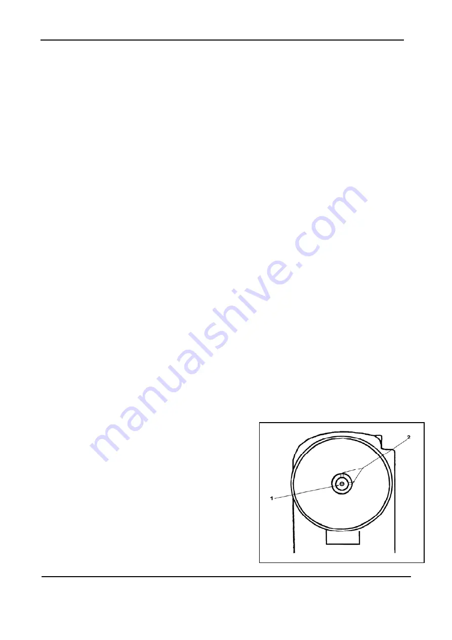
Adjustment of needle bar stop position
1)Adjust of "UP" position
When the pedal is kicked down by heel, the machine
stops at "UP" position. If the marks deviate larger than
3mm adjust as follows.
(1)Loosen the screw1 and 2
,
Summary of Contents for GC1998-MCDZ
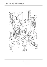
Page 13: ...A ARM BED AND ITS ACCESSORIES 11...
Page 16: ...B NEEDLE BAR AND THREAD TAKE UP MECHANISM 14 14...
Page 18: ...C FEEDING AND FEED LIFTING MECHANISM 16 16...
Page 21: ...D STITCH REGULATOR MECHANISM 19 19...
Page 24: ...E KNIFE MECHANISM 22...
Page 26: ...F PRESSER FOOT MECHANISM 24 24...
Page 29: ...G THREAD TRIMMER MECHANISM 27 27...
Page 32: ...H TOUCH BACK AND DETECTOR MECHANISM 30 30...
Page 34: ...I MOTOR MECHANISM 32 32...
Page 36: ...J OIL LUBRICATION MECHANISM 34 34...
Page 38: ...K ACCESSORIES 36 36...


